Height-adjustable LED light post

A technology for LED lights and height adjustment, which is applied to parts of lighting devices, semiconductor devices of light-emitting elements, outdoor lighting, etc. Effect

Inactive Publication Date: 2019-01-25
饶品魁
View PDF3 Cites 2 Cited by
  • Summary
  • Abstract
  • Description
  • Claims
  • Application Information

AI Technical Summary

Problems solved by technology

[0005] Aiming at the deficiencies of the prior art, the present invention provides a height-adjustable LED light pole, which has the advantage of being convenient for adjusting the height of the LED light, and solves the problem that the existing LED light poles are usually fixed and cannot adjust the height of the LED light. The height adjustment problem

Method used


Image

  • Height-adjustable LED light post
  • Height-adjustable LED light post
  • Height-adjustable LED light post

Examples


Embodiment 2

[0036] Embodiment 2: The difference from Embodiment 1 is that the transmission mechanism 10 includes a worm wheel 101, a worm screw 102 and an L-shaped handle 103, and the worm screw 102 is movably connected to the right side of the inner wall of the transmission box 2 through a bearing, and the worm screw 102 is located behind the screw rod 1 4 side, the worm wheel 101 is fixedly connected to the surface of the screw 14, the worm 102 meshes with the worm wheel 101, the L-shaped handle 103 is arranged on the left side of the transmission box 2, and the right end of the worm 102 penetrates to the right side of the transmission box 2 and is fixedly connected to the The top of the right side of the L-shaped handle 103, by setting the worm gear 101 and the worm screw 102, can drive the screw rod 14 to rotate, reduce the rotation speed of the screw rod 14, and improve the transmission strength of the L-shaped handle 103 to the screw rod 4, The screw rod-4 is more stable when rotatin...

Embodiment 3

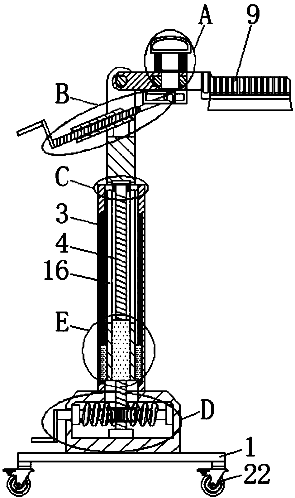
[0037] Embodiment 3: The difference from Embodiment 1 is that the bottoms on both sides of the transmission cylinder 6 are fixedly connected with sliders 11, and both sides of the inner wall of the support cylinder 3 are provided with chute 12, and the sliders 11 are slidably connected to the sides of the chute 12. Inside, the inside of the chute 12 is vertically fixedly connected with a slide bar 13, and the slide block 11 is sleeved on the surface of the slide bar 13. By setting the slide block 11 and the chute 12, the screw sleeve 1 can be limited to prevent the screw sleeve from The sleeve-5 rotates when moving up and down, which improves the stability of the screw sleeve-5 when moving.

Embodiment 4

[0038] Embodiment 4: The difference from Embodiment 1 is that the top of the surface of the screw rod 4 is movably connected with the limit sleeve 14 through bearings, and both sides of the limit sleeve 14 are fixedly connected with the limit plate 15, and both sides of the transmission cylinder 6 are equipped with Opening 16, the limit plate 15 passes through the opening 16 away from the side of the limit sleeve 14 and is fixedly connected with the inner wall of the support tube 3. By setting the limit sleeve 14 and the limit plate 15, the top of the screw rod-4 can be fixed. The degree of support avoids the phenomenon that the screw rod-4 shakes when it rotates, and improves the stability of the screw rod-4 when it rotates.


PUM


Abstract

The invention discloses a height-adjustable LED light post, comprising a bed plate. A transmission case is fixedly connected to the top of the bed plate, a support tube is welded to the top of the transmission case, the bottom end of the support tube is communicated with the top of the transmission case, the bottom of the inner wall of the transmission case is movably connected with a first screwthrough a bearing, and the top end of the first screw extends to the inside of the support tube. A transmission mechanism drives the first screw to rotate, the first screw can drive a transmission cylinder to move up and down through a first nut, and the transmission cylinder moves up and down while driving an LED light body to move up and down through a connecting plate and a square plate. Therefore, the LED light post has the advantage of realizing height adjusting, solves the problem of failure in adjusting height of the conventional LED light post which is of fixed arrangement, also avoidsthe problem of single function due to the fact that lighting range of the LED light is inconvenient to adjust due to failure in height adjustment of the LED light post, and brings convenience to users.

Description

technical field [0001] The invention relates to the technical field of LED lamps, in particular to a height-adjustable LED lamp post. Background technique [0002] LED is a solid-state semiconductor device that can convert electricity into visible light, and can directly convert electrical energy into light energy. LED lights are usually a collection of multiple LED combinations. [0003] With the development of science and technology and the improvement of people's quality of life, more and more LED lights have entered our lives. These LED lights also play a decorative role while illuminating, but the existing LED light poles are usually fixed. The height of the LED lamp cannot be adjusted, which makes it inconvenient to adjust the illumination range of the LED lamp. The function is relatively single, and it is not convenient for people to use. Contents of the invention [0004] (1) Solved technical problems [0005] Aiming at the deficiencies of the prior art, the pres...

Claims


Application Information

Patent Timeline
Patent Type & Authority Applications(China)
IPC IPC(8): F21S8/08F21V14/02F21V21/22F21W131/103F21Y115/10
CPCF21S8/085F21V14/02F21V21/22F21W2131/103F21Y2115/10
Inventor 饶品魁
Owner 饶品魁
Why Eureka
Try Eureka