Hose sealability detection device

A technology for leak detection and rubber hose, which is applied in fluid tightness testing, measuring devices, liquid tightness measurement using liquid/vacuum degree, etc. It can solve problems such as low accuracy, low work efficiency, and poor sealing performance , to achieve the effect of increasing air tightness, improving efficiency and simple structure

Inactive Publication Date: 2019-01-25
扬州尚翔汽车零部件有限公司
View PDF0 Cites 3 Cited by
  • Summary
  • Abstract
  • Description
  • Claims
  • Application Information

AI Technical Summary

Problems solved by technology

If the sealing performance of the rubber hose is not good, when the rubber hose is used to transmit oil, water and other media, leakage will occur, affecting normal use
At present, there are mainly three detection methods for rubber hoses. One is that the operator manually flattens the rubber hose to see if it is broken or cracked. The detection efficiency is low and the accuracy is low; the other is to put the rubber hose in water and inflate it. Observe the bubbles on the surface of the rubber tube. When the water quality is turbid for many times, the bubbles are not easy to be observed; there is another way to directly inject water into the rubber tube to check whether there is any water leakage. After the test is completed, the inside of the square tube needs to be cleaned and dried. The steps are cumbersome and the work efficiency is too low, therefore, further improvement is needed

Method used


Image

  • Hose sealability detection device
  • Hose sealability detection device
  • Hose sealability detection device

Examples


Embodiment Construction

[0017] The preferred embodiments of the present invention will be described below in conjunction with the accompanying drawings. It should be understood that the preferred embodiments described here are only used to illustrate and explain the present invention, and are not intended to limit the present invention.

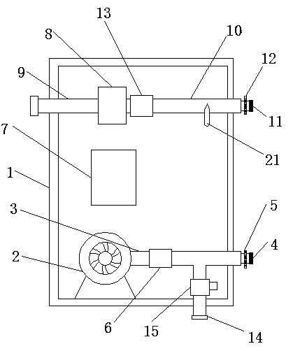
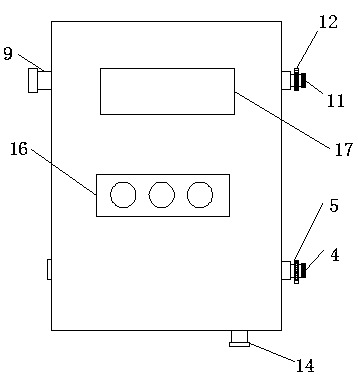
[0018] Such as Figure 1-Figure 3 As shown, the rubber hose tightness detection device includes a box body 1, an air pump 2 is provided at the bottom of the inner cavity of the box body 1, and the air outlet of the air pump 2 is connected to a first guide tube 3, and the first guide tube The other end of the pipe 3 is installed on one side of the box body 1, a first sealing ring 4 is provided at the port of the first diversion pipe 3, and a first hose clamp 5 is provided on one side of the first sealing ring 4, and the rubber hose is added. The airtightness of the connection prevents the impact on the detection data. The first guide pipe 3 is provided with the first...


PUM


Abstract

The present invention relates to a hose sealability detection device. The device comprises a box body; an air inflation pump is arranged at the bottom of the inner cavity of the box body; the air outlet of the air inflation pump is connected with a first flow guide tube; one end of the first flow guide tube passes through the other side of the box body; a first sealing ring is disposed at the end opening of the first flow guide tube; a first hose clamp is arranged to one side of the first sealing ring; the first flow guide tube is provided with a first check valve and a pressure relief tubewhich are sequentially arranged from the left side to the right side of the first flow guide tube; one end of the pressure relief tube passes through the lower end of the box body; the pressure relieftube is provided with a solenoid valve; a PLC is disposed above the air inflation pump; a water pump is arranged above the PLC; one side of the water pump is connected with a water incoming tube; thewater incoming tube passes through the top of one side of the box body; and the other side of the water pump is connected with a second flow guide tube. The hose sealability detection device has theadvantages of simple structure and reasonable design. With the hose sealability detection device of the invention adopted, a method that applies direct water injection to realize detection can be avoided, a drying step can be eliminated, work efficiency can be improved, and a leak point can be tracked when a hose leaks.

Description

technical field [0001] The invention relates to a rubber hose tightness detection device, which belongs to the field of rubber hose quality detection devices. Background technique [0002] Rubber is an indispensable material for social development, and it is a high-elastic polymer compound. Rubber products are widely used in various aspects of industry or life. Since the rubber parts are organic materials, the final product needs to be tested for quality. If the sealing performance of the rubber hose is not good, when the rubber hose is used to transmit oil, water and other media, leakage will occur, which will affect normal use. At present, there are mainly three detection methods for rubber hoses. One is that the operator manually flattens the rubber hose to see if it is broken or cracked. The detection efficiency is low and the accuracy is low; the other is to put the rubber hose in water and inflate it. Observe the bubbles on the surface of the rubber tube. When the w...

Claims


Application Information

Patent Timeline
Patent Type & Authority Applications(China)
IPC IPC(8): G01M3/28
CPCG01M3/2815
Inventor 成岗
Owner 扬州尚翔汽车零部件有限公司
Why Eureka
Try Eureka