
Front cassette type jack and tool anchorage equipment for prestress tension

A jack and tool anchor technology, which is applied in the field of bridge prestress tension test, can solve the problem of inability to detect the retraction amount of tool clips, and achieve the effect of improving tensioning efficiency and tensioning control accuracy and saving steel strands

Active Publication Date: 2019-01-25
WUHAN SIMUTECH CO LTD
View PDF11 Cites 6 Cited by
  • Summary
  • Abstract
  • Description
  • Claims
  • Application Information

AI Technical Summary

Problems solved by technology

[0010] In the above schemes, oil pressure is used to detect the tension force, and the retraction of the tool clip cannot be detected at the same time.

Method used


Image

  • Front cassette type jack and tool anchorage equipment for prestress tension
  • Front cassette type jack and tool anchorage equipment for prestress tension
  • Front cassette type jack and tool anchorage equipment for prestress tension

Examples


Embodiment 1

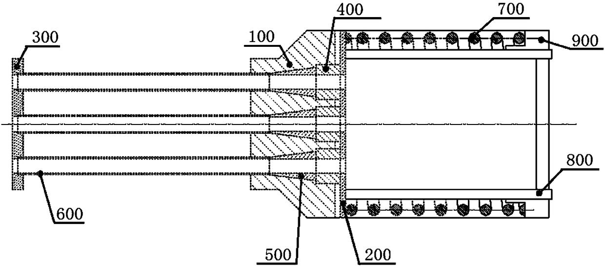
[0052] Such as figure 2 As shown, the front clamp tool anchor device includes a tool anchor plate 100, a front push plate 200, a push back plate 300, a push sleeve 400, a tool clip 500, a push back rod 600, a push spring 700 and a retraction probe rod 800; the rear end of the tool anchor plate 100 is provided with the front push plate 200, and the front end of the tool anchor plate 100 is provided with the push back plate 300; the tool anchor plate 100 is provided with a through hole; One end of the front push sleeve 400 is installed at the rear end in the through hole, and the other end of the front push sleeve 400 is located outside the through hole and connected with the front push plate 200; the tool clip 500 is installed In the middle of the through hole, it is connected to one end of the forward push sleeve 400 located in the through hole; one end of the push back rod 600 passes through the push back plate 300, and the push back rod 600 passes through the push back plat...

Embodiment 2

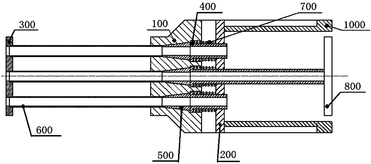
[0056] Such as image 3 As shown, the front clamp tool anchor device includes a tool anchor plate 100, a front push plate 200, a push back plate 300, a push sleeve 400, a tool clip 500, a push back rod 600, a push spring 700 and a retraction probe rod 800; the rear end of the tool anchor plate 100 is provided with the front push plate 200, and the front end of the tool anchor plate 100 is provided with the push back plate 300; the tool anchor plate 100 is provided with a through hole; One end of the front push sleeve 400 is installed at the rear end in the through hole, and the other end of the front push sleeve 400 is located outside the through hole and connected with the front push plate 200; the tool clip 500 is installed In the middle of the through hole, it is connected to one end of the forward push sleeve 400 located in the through hole; one end of the push back rod 600 passes through the push back plate 300, and the push back rod 600 passes through the push back plate...


PUM


Abstract

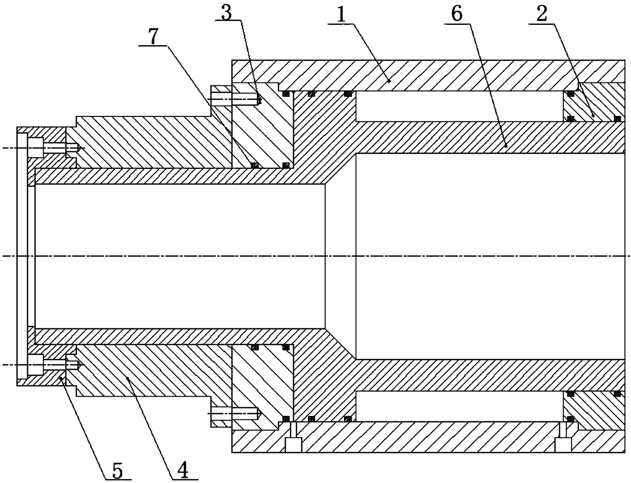
The invention relates to a front cassette type jack and tool anchorage equipment for prestress tension. The equipment comprises a front clamping type tool anchorage device and a front cassette type jack with a force measurement sensor, wherein the front clamping type tool anchorage device includes a tool anchorage disc, a front push plate, a back push plate, a tool clamping sheet, a back-push rod,a forward push spring and a retraction amount feeler lever; the front cassette type jack includes a jack outer cylinder, a jack back baffle plate, a jack front baffle plate, the force measurement sensor, a limiting plate mounting seat and a jack piston; the front clamping type tool anchorage device is sleeved in the jack piston of the front cassette type jack. According to the front cassette typejack and tool anchorage equipment for prestress tension, while a steel strand is saved, the retraction amount of the tool clamping sheet can be detected through the retraction amount feeler lever, thus the tension efficiency and the tension control precision can be improved.

Description

technical field [0001] The invention relates to the field of bridge prestress tension test, in particular to a front clip jack and tool anchor equipment for prestress tension. Background technique [0002] The jack used in traditional prestressed bridge tensioning is a through-hole jack. When it is working, the steel strands, working anchors and working clips will be encapsulated in the prestressed member after the tensioning is completed; Before the steel strand is packaged, 5-10mm will be left outside the working clip, and the rest will be cut off. The cut steel strand will be treated as scrap steel. A railway beam yard can waste up to More than 1 million yuan. [0003] In order to reduce the waste of steel strands, various tensioning equipment suppliers have proposed a variety of tensioning jack schemes (front clip jacks) to save the reserved amount of steel strands. A common feature of all the schemes is to make the tool anchor and The tool clip is sunk into the inside...

Claims


Application Information

Patent Timeline
IPC IPC(8): G01N3/08E01D21/00E01D101/28
CPCE01D21/00E01D2101/28G01N3/08
Inventor 周晓杨邓仁堂刘新平肖路明
Owner WUHAN SIMUTECH CO LTD
Learn More