Electric energy distribution system and a distribution method based on an intelligent electric room

A technology of electric energy distribution and smart electric room, applied in the field of power grid, can solve the problems of large power consumption, expensive electricity bills, and insufficient power

Active Publication Date: 2019-01-25
佛山市智阳能源有限公司
View PDF4 Cites 7 Cited by
  • Summary
  • Abstract
  • Description
  • Claims
  • Application Information

AI Technical Summary

Problems solved by technology

[0002] The electricity consumption of factories in industrial areas is of a commercial nature and consumes a lot of electricity, so the electricity bills are relatively expensive. In order to reduce these expenses, many factories will choose to install photovoltaic power stations on the roof to reduce electricity consumption. However, under normal circumstances, photovoltaic The power generation of the power station often cannot meet the needs of the factory building. This is because the power generation of the photovoltaic power station is affected by the weather, the structure of the roof, and also affected by the surrounding obstacles to varying degrees. Although the power generation of the factory building is greatly reduced. The power consumption of the public grid, but generally for the factory building, the power is still not enough in many cases
[0003] With the general trend of energy saving and emission reduction, more and more ordinary families will install photovoltaic power stations on their roofs, because it can not only play the role of sunshade and heat insulation, but also generate electricity for their own use. Since the electricity consumption of ordinary families is not large, Often there will be excess electricity, and these excess electricity will enter the public grid, which shows that the electricity of these photovoltaic power plants cannot be fully utilized

Method used


Image

  • Electric energy distribution system and a distribution method based on an intelligent electric room
  • Electric energy distribution system and a distribution method based on an intelligent electric room

Examples


Embodiment Construction

[0026] The present invention provides an electric energy distribution system and distribution method based on an intelligent electric room. In order to make the purpose, technical solution and effect of the present invention clearer and clearer, the present invention will be further described in detail below with reference to the accompanying drawings and examples. It should be understood that the specific embodiments described here are only used to explain the present invention, not to limit the present invention.

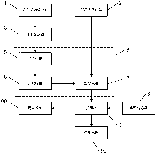
[0027] see Figure 1-2 , an electric energy distribution system based on a smart power room provided by the present invention, including a distributed photovoltaic power station 1, a factory photovoltaic power station 2, a step-up transformer 3, a smart power room A, and a grid-connected cabinet installed in an ordinary power room of the factory 4. The smart electric room A is equipped with a switch electric cabinet 5, a metering electric cabinet 6 and a collectio...


PUM


Abstract

The invention provides an electric energy distribution system and a distribution method based on an intelligent electric room. The electric energy distribution system comprises a distributed photovoltaic power station, a factory photovoltaic power station, a step-up transformer, an intelligent electric room and a grid-connected cabinet. A switch electric cabinet, a metering electric cabinet and asummary electric cabinet are arranged in that intelligent electric room; The distributed photovoltaic power station comprises a plurality of residential roof photovoltaic power stations; The distributed photovoltaic power station, the booster transformer, the switch cabinet and the metering cabinet are electrically connected in turn, and the factory photovoltaic power station, the metering cabinetand the grid-connected cabinet are electrically connected with the aggregation cabinet; The summary cabinet is used for summarizing and monitoring the power generation quantity, and distributing andtransferring the power quantity to the grid-connected cabinet; The grid-connected cabinet is used for controlling the transmission of electric energy to the electric equipment or the utility grid of the factory according to the electric situation of the electric equipment of the factory. The distribution system and the distribution method can make the electricity of the photovoltaic power stationon the roof of the residents around the factory be more fully utilized, and can reduce the electricity cost of the factory at the same time.

Description

technical field [0001] The invention relates to the technical field of electric power grids, in particular to an electric energy distribution system and distribution method based on an intelligent electric room. Background technique [0002] The electricity consumption of factories in industrial areas is of a commercial nature and consumes a lot of electricity, so the electricity bills are relatively expensive. In order to reduce these expenses, many factories will choose to install photovoltaic power stations on the roof to reduce electricity consumption. However, under normal circumstances, photovoltaic The power generation of the power station often cannot meet the needs of the factory building. This is because the power generation of the photovoltaic power station is affected by the weather, the structure of the roof, and also affected by the surrounding obstacles to varying degrees. Although the power generation of the factory building is greatly reduced. The power cons...

Claims


Application Information

Patent Timeline
Patent Type & Authority Applications(China)
IPC IPC(8): H02J3/38
CPCH02J3/383Y02B10/10Y02E10/56Y02P80/20
Inventor 潘松振
Owner 佛山市智阳能源有限公司
Why Eureka
Try Eureka