Blowing device and cleaner

A technology of air supply device and top plate, applied in the direction of vacuum cleaner, cooling/ventilation device, pump device, etc., can solve the problems of unbalance, difficult to correct efficiently, etc., and achieve the effect of correcting unbalance

Active Publication Date: 2019-01-29
NIDEC CORP
View PDF6 Cites 3 Cited by
  • Summary
  • Abstract
  • Description
  • Claims
  • Application Information

AI Technical Summary

Problems solved by technology

[0004] However, in the electric blower described in Japanese Laid-Open Publication No. 2003-129995, there is a problem that it is difficult to efficiently correct the unbalance.

Method used


Image

  • Blowing device and cleaner
  • Blowing device and cleaner
  • Blowing device and cleaner

Examples


Embodiment Construction

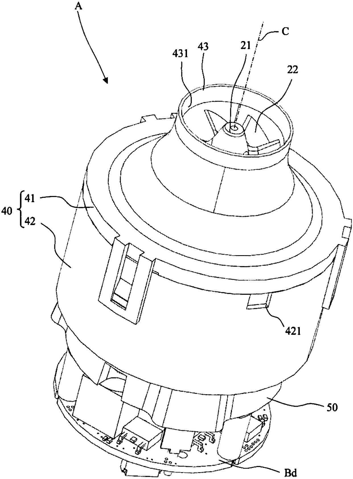
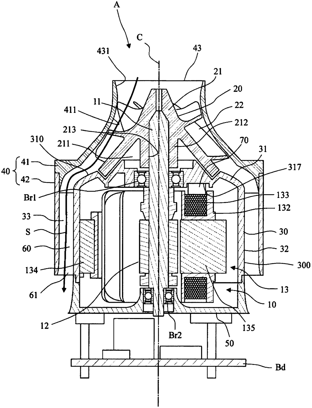
[0026] Hereinafter, exemplary embodiments of the present invention will be described in detail with reference to the drawings. In addition, in this specification, in the air blower A, the direction parallel to the central axis C of the air blower A is called "axial direction", and the direction perpendicular to the central axis C of the air blower A is called "axial direction". "radial direction" refers to a direction along an arc centered on the central axis C of the air blower A as a "circumferential direction". Similarly, with regard to the impeller 20, the directions that coincide with the axial direction, radial direction, and circumferential direction of the air blower A in the state assembled in the air blower A are also simply referred to as "axial", "radial" and "direction" respectively. "Zhou Xiang". In addition, in this specification, in the blower A, the shape and positional relationship of each part will be described with the axial direction being the vertical di...


PUM


Abstract

A blowing device (A) includes an impeller (20) capable of rotating about a central axis (C); a motor (10) disposed below the impeller (20) in a central axis direction and rotating the impeller (20); and a motor housing (30) surrounding the motor (10). The motor housing (30) includes a motor housing top plate (31) expanding in a direction orthogonal to the central axis (C) and facing a lower surface of the impeller (20), and a motor housing cylindrical portion (32) extending downwardly in the axial direction from an outer edge of the motor housing top plate (31) in a radial direction. A top plate recess portion (313) extending from the outer edge of the motor housing top plate (31) in the radial direction to an inside in the radial direction and recessed downwardly is formed on an upper surface of the motor housing top plate (31).

Description

technical field [0001] The invention relates to an air supply device and a vacuum cleaner comprising the air supply device. Background technique [0002] In general, an electric blower (blower) used for an electric vacuum cleaner or the like rotates at a high speed, and therefore tends to vibrate due to an imbalance in the rotating part. Therefore, Japanese Laid-Open Patent Publication No. 2003-129995 discloses an electric blower (blower) capable of eliminating the unbalance of the rotating portion. [0003] The electric blower disclosed in Japanese Laid-Open Publication No. 2003-129995 includes a rotating fan and an asymmetrical ring-shaped unbalanced member, and the unbalanced member penetrates the rotating shaft at an appropriate position on the outer peripheral surface of the rotating shaft. Instead, it is installed at a position opposite to the unbalanced position of the rotor. Accordingly, it is claimed that the initial unbalance amount of the rotor can be reduced. ...

Claims


Application Information

Patent Timeline
Patent Type & Authority Applications(China)
IPC IPC(8): A47L5/22A47L9/00A47L9/02
CPCA47L5/22A47L9/00A47L9/02H02K5/207H02K5/04H02K7/04H02K9/14H02K15/165A47L5/24F04D17/165F04D25/0606F04D29/281F04D29/4253
Inventor 盐泽和彦早光亮介
Owner NIDEC CORP
Why Eureka
Try Eureka