A method and device for charging an electric energy storage system in a vehicle

a technology of electric energy storage and which is applied in the direction of electric devices, battery/fuel cell control arrangements, electric devices, etc., can solve the problems of reducing the capacity reducing the usability of the electric energy storage system, and affecting the operation of the vehicle, so as to improve the usability of the electric propulsion system and improve the usability of the vehicl

Active Publication Date: 2017-11-30
VOLVO LASTVAGNAR AB
View PDF2 Cites 2 Cited by
  • Summary
  • Abstract
  • Description
  • Claims
  • Application Information

AI Technical Summary

Benefits of technology

[0004]The charging of batteries may generally be divided into two different kinds of charging: “Plug-in” charging by connecting the vehicle to the net when the vehicle is parked and charging under driving conditions, e.g. by regenerative braking. In general, the ESS may be charged to a higher SOC level when it is recharged at standstill from a fixed electrical power source than when recharged during travel, e.g. by regenerative braking. When the vehicle is parked and charged by a plug-in connection is it in general desired to (large the battery up to the maximum charging limit such that the electrical energy storage comprises maximum energy before starting. Still another advantage is that for certain batteries is it beneficial to provide maintenance and monitoring of the battery when it is fully charged, e.g. to correct imbalance of the battery and check other battery status values such as maximum State Of Charge (SOC) level and to monitor if the storage capacity has deteriorated. When the vehicle has been plugged in for sufficient time, the battery is thus charged to the desired level and ready to be used when the vehicle is started again. In US 2012 / 006866 is disclosed an example of how an ESS may be controlled and charged.
[0005]The present invention is directed to the control of the charging and discharging of the Energy Storage System (ESS) in an electrical propulsion system for a vehicle in order to improve the usability of the electrical propulsion system and thus the overall performance of the vehicle, e.g. a heavy duty HEV.
[0006]It is desirable to provide a method which improves the usability of a vehicle comprising an electrical Energy Storage System (ESS) in an electrical propulsion system by controlling the charging and discharging of the battery to be within desired State Of Charge (SOC) limits. The invention is in particular directed to the control of the SOC level of the battery when charging the battery in a parked mode, i.e. a so called “plug-in” charge using electricity from the net, and to monitor and perform maintenance of the battery before and at start-up of the vehicle after charging of the battery.

Problems solved by technology

There is in general a set limit of how much a battery may be charged before it will be damaged.
To maintain the ESS at a high SOC level, e.g. above the maintenance limit, as a storage SOC level of the ESS may have a negative impact on the functionality of the ESS and reducing its capacity and shorten its life cycle.
In many cases is there no other possibility to slow down an EM than applying an electrical load why the operation of the vehicle may suffer if a braking action not is possible for the EM.
If the SOC level is set to be too high, regenerative braking may not be possible to use or only be used with a limited braking force, which may negatively influence desired driving characteristics.
The predictive driving sequence may be hard to predestine for a longer time.

Method used


Image

  • A method and device for charging an electric energy storage system in a vehicle
  • A method and device for charging an electric energy storage system in a vehicle
  • A method and device for charging an electric energy storage system in a vehicle

Examples


Embodiment Construction

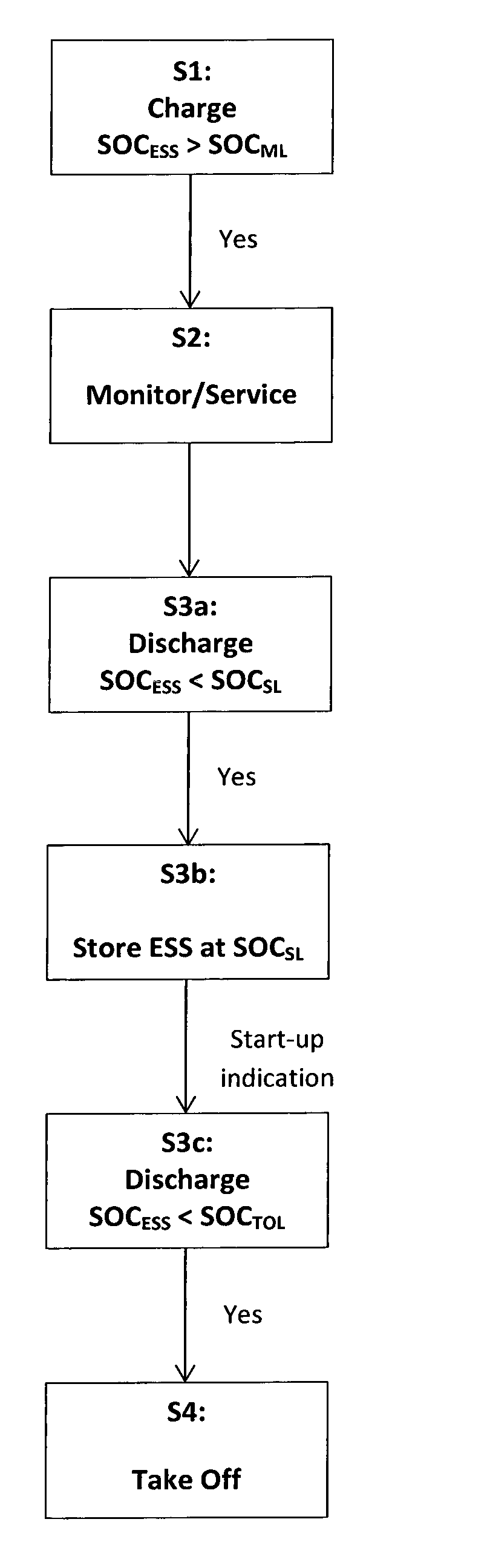
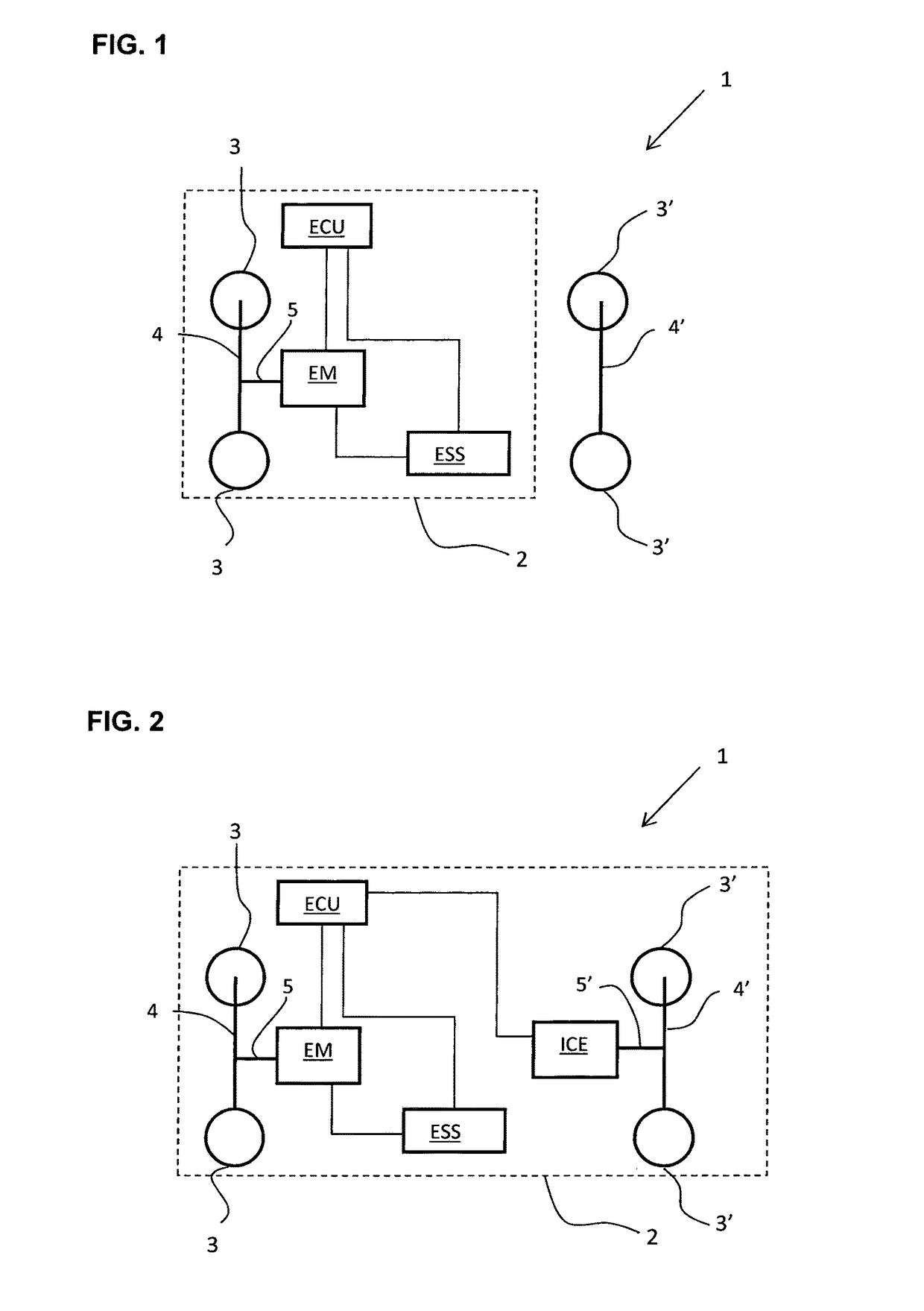
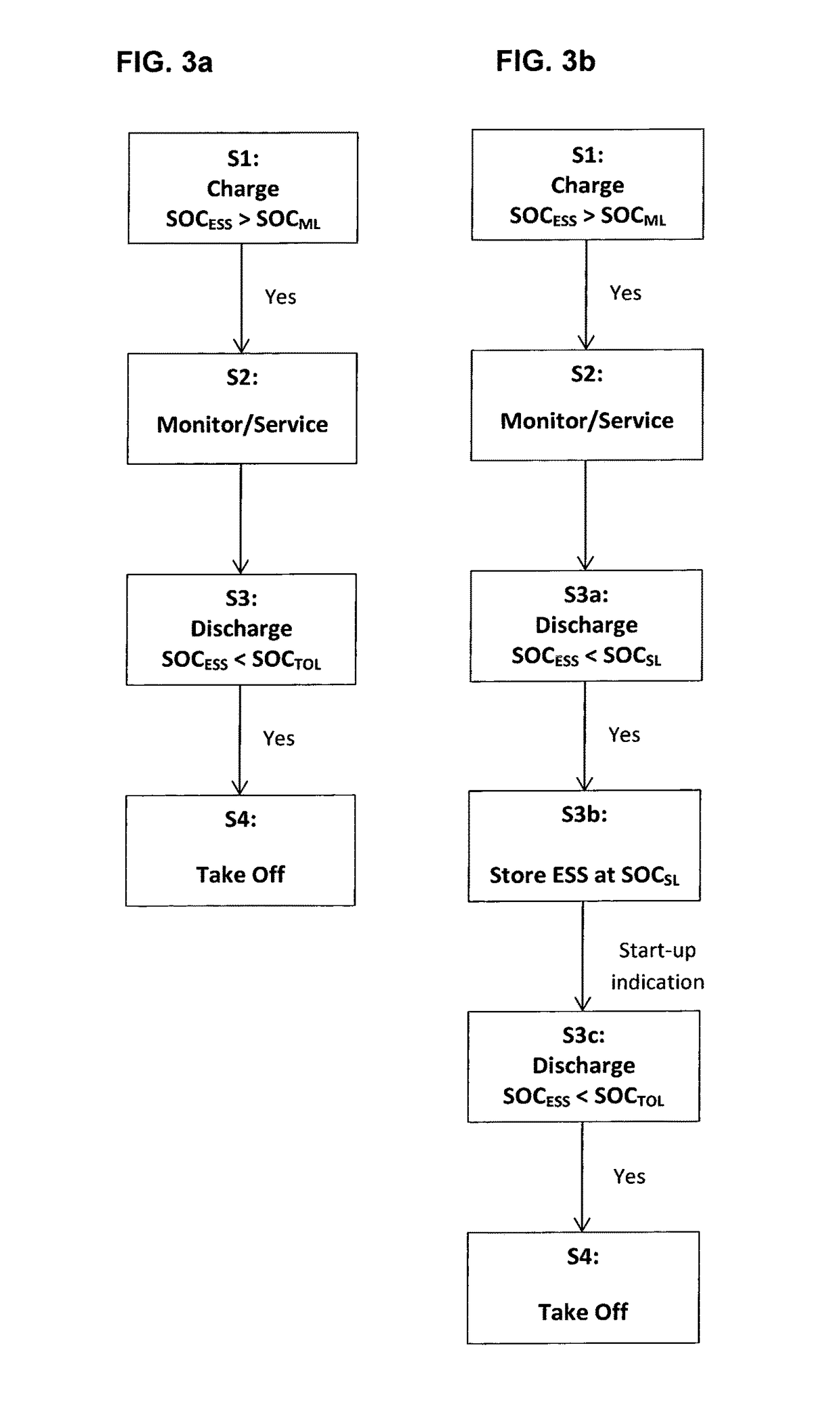
[0031]In FIG. 1 is shown a vehicle I comprising an electric propulsion system 2. The electric propulsion system 2 comprises a pair of driven wheels 3 attached to a driven axle 4 which is drivingly connected to an output shaft 5 of an Electric Motor (EM). The Electric Motor (EM) is electrically connected to an electric Energy Storage System (ESS) for powering the electric motor (EM). The electric propulsion system 2 further comprises an Electronic Control Unit (ECU) connected to the electric Energy Storage System (ESS) and the Electric Motor (EM) in order to monitor and / or control the ESS and EM. The vehicle I further comprises a second pair of wheels 3′ connected to a second axle 4′ which wheels 3′ not are driven.

[0032]The above described vehicle is only intended to serve as an example of an Electric Vehicle (EV) suitable for the control system according to the invention. The system may be modified, e.g. may the Electric Motor (EM) also be drivingly connected to the second axle 4′ s...


PUM


Abstract

A device/method for the control of a charge operation and the State Of Charge (SOC) of an electrical Energy Storage System (ESS), e.g. a battery, that includes a multitude of cells is provided. The ESS is electrically connected to a propulsion system of a vehicle in order to power an Electric Motor. The method includes charging the ESS from an electrical power source, e.g., the grid, when the vehicle is at standstill, stopping the charging when the SOC level of the ESS is above a maintenance limit for the SOC level of the ESS, monitoring the battery and/or performing a service operation of the ESS after the ESS has been charged to a SOC level above the maintenance limit for the SOC level of the ESS, deliberately discharging the ESS to lower the SOC level. The SOC level of the ESS is reduced to a take-off limit for the SOC level of the ESS which is set in order to allow the vehicle to be controlled to use regenerative braking for charging of the ESS under subsequent driving when the vehicle is restarted and takes off.

Description

BACKGROUND AND SUMMARY[0001]The invention relates to a method and device for control of charging, discharging and State of Charge (SOC) of an electric Energy Storage System (ESS), e.g. a battery, in a vehicle. The method is suitable to be used for the control of an ESS for powering the electric powertrain of a Hybrid Electric Vehicle (HEV), e.g. a heavy-duty vehicle such as a truck, bus or construction equipment. Although the invention will be described with respect to a heavy duty HEV, the invention is not restricted to this particular kind of vehicle, but may also be used in lighter vehicles provided with an electrical powertrain, e.g. a personal car of the HEV-type. The method is also suitable furan Electric Vehicle (EV).[0002]In order to improve fuel efficiency and provide propulsion systems having less negative impact on the environment, there is a tendency to modify common propulsion systems, using only Internal Combustion Engines (ICE), with Electrical Motors (EM). The vehicl...

Claims


Application Information

Patent Timeline
Patent Type & Authority Applications(United States)
IPC IPC(8): B60L11/18B60L3/00B60L7/10
CPCB60L11/1862B60L11/1809B60L7/10Y10S903/903B60L2240/54B60L2240/42B60L2260/22B60L3/0046B60L53/00B60L58/12B60L2200/36B60L2200/40B60L2260/26B60L15/2072B60L50/16B60L50/51B60L58/13B60L58/15Y02T10/64Y02T10/70Y02T10/7072Y02T10/72Y02T90/14
Inventor SMIDEBRANT, TOBIAS
Owner VOLVO LASTVAGNAR AB
Why Eureka
Try Eureka