Rolling rod steel bar machining device

A steel bar processing and rolling bar technology, which is applied in the field of rolling bar steel bar processing devices, can solve problems affecting transportation efficiency, on-site material waste, and steel bar damage, and achieve the effects of improving transportation efficiency, reducing friction, and improving efficiency

Inactive Publication Date: 2019-01-29
CHINA HUAYE GROUP +1
View PDF6 Cites 0 Cited by
  • Summary
  • Abstract
  • Description
  • Claims
  • Application Information

AI Technical Summary

Problems solved by technology

However, in the long-term construction and practice, it has been found that the steel bar processing platform under the above-mentioned prior art needs to be transported through the workbench when it is used for processing long steel bars. to the location, and during the transportation process, the friction between the steel bar itself and the workbench surface, on the one hand, affects the transportation efficiency, and then affects the processing cycle; on the other hand, the friction force in the transportation process causes the steel bar itself to damage, and when the friction force is large, it also poses hidden dangers to the construction safety of construction workers working at heights
[0005] In addition, in order to ensure the strength of the steel bar processing workbench in the prior art, steel bars or steel scaffolding welding wires are usually used to connect and fix the workbench. When the construction of this floor is completed and transferred to the next floor, the processing workbench cannot After dismantling, it will be transferred and reused. In this way, materials on site will be wasted, and the workbench needs to be welded again after construction on the next floor, which also affects the construction period to a certain extent and reduces the construction efficiency of construction personnel.

Method used


Image

  • Rolling rod steel bar machining device
  • Rolling rod steel bar machining device

Examples


Embodiment Construction

[0015] An embodiment of a rolling bar steel bar processing device according to the present invention will be described below with reference to the accompanying drawings. As those skilled in the art would realize, the described embodiments may be modified in various different ways, all without departing from the spirit and scope of the present invention. Accordingly, the drawings and description are illustrative in nature and not intended to limit the scope of the claims. Also, in this specification, the drawings are not drawn to scale, and like reference numerals denote like parts.

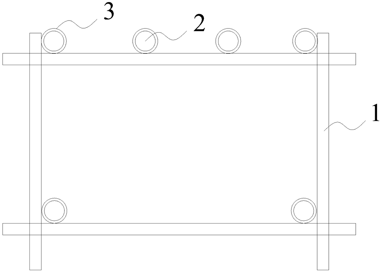
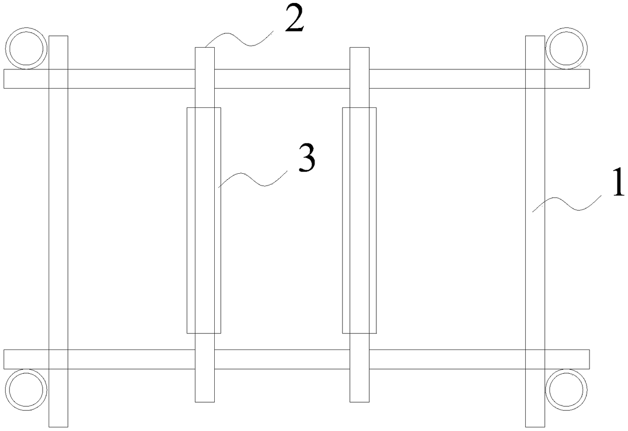
[0016] figure 1 It is a side view, showing a schematic side view of the rolling bar steel bar processing device described in one embodiment of the present invention. figure 2 is a top view, showing the figure 1 The top view structure of the rolling bar rebar processing device shown. see figure 1 and figure 2 , the rolling bar reinforcement processing device described in this embodiment of ...


PUM


Abstract

The invention provides a rolling rod steel bar machining device. The rolling rod steel bar machining device comprises a supporting frame, a plurality of fixing rods and a plurality of rolling rods, wherein the fixing rods extend in the width direction of the top surface of the supporting frame and stretch across the portion above the supporting frame, the rolling rods and the fixing rods are in one-to-one correspondence, the rolling rods sleeve outside the fixing rods so that the rolling rods can rotate by taking the fixing rods as the axes, and the plurality of rolling rods form a machining table on the top surface of the supporting frame. When the rolling rod steel bar machining device is used, steel bars to be machined are placed on the plurality of rolling rods in the length directionof the top of the supporting frame, the steel bars are pushed so as to roll on the plurality of rolling rods, rolling of the steel bars is easy to achieved, the friction force between the steel bars and a working table can be effectively reduced, then the conveying efficiency of the steel bars in the steel bar machining process is improved, and the steel bar machining efficiency is also remarkablyimproved; and moreover, the construction safety in the steel bar machining process can be effectively guaranteed by reducing the friction force between the steel bars and the working table.

Description

technical field [0001] The invention relates to the technical field of on-site processing tools for steel bars, in particular to a rolling bar steel bar processing device. Background technique [0002] Steel structure engineering is a structure mainly made of steel. It is mainly composed of steel beams, steel columns, steel trusses and other components made of steel and steel plates. The components or parts are usually connected by welds, bolts or rivets. One of the main types of building structures. Because of its light weight and easy construction, it is widely used in large factories, bridges, stadiums, super high-rises and other fields. [0003] A large number of steel bars are used in the construction of steel structures, and the steel bars need to be straightened, cut, rolled, and bent according to specific requirements during the construction process. Due to the continuous increase of the indoor floor height under the prior art, and the increased position of the rei...

Claims


Application Information

Patent Timeline
IPC IPC(8): B21F23/00
Inventor 张春新
Owner CHINA HUAYE GROUP
Why Eureka
Try Eureka