
Girth welding tool

A circular seam welding and tooling technology, which is applied in welding equipment, auxiliary welding equipment, welding/cutting auxiliary equipment, etc., can solve the problems of difficult adjustment of fixed welding position, affecting the efficiency of workpiece welding, and difficult adjustment of workpiece, etc., and achieves improvement. Improve welding quality, increase welding speed, and ensure the effect of welding quality

Pending Publication Date: 2019-01-29
天津市武清区环球锌业有限公司
View PDF10 Cites 1 Cited by
  • Summary
  • Abstract
  • Description
  • Claims
  • Application Information

AI Technical Summary

Problems solved by technology

The level of welding process equipment has become a standard to measure a country's industrial level. Welding equipment is developing towards mechanization and standardization, and is constantly being improved. The existing welding equipment generally adopts clamping type, which is directly clamped and fixed by clamping blocks. The workpiece, the workpiece is not easy to adjust on the tooling, and it is not easy to adjust the fixed welding position. The worker needs to constantly adjust the workpiece when welding, which is very troublesome to operate, and it is easy to cause welding interruption, which greatly affects the efficiency of workpiece welding

Method used


Image

  • Girth welding tool
  • Girth welding tool
  • Girth welding tool

Examples


Embodiment Construction

[0021] It should be noted that the embodiments of the present invention and the features in the embodiments can be combined with each other if there is no conflict.

[0022] In the description of the present invention, it should be understood that the terms "center", "longitudinal", "transverse", "upper", "lower", "front", "rear", "left", "right", " The orientation or positional relationship indicated by "vertical", "horizontal", "top", "bottom", "inner", "outer" etc. is based on the orientation or positional relationship shown in the drawings, and is only for the convenience of describing the present invention and The description is simplified, rather than indicating or implying that the pointed device or element must have a specific orientation, be constructed and operated in a specific orientation, and therefore cannot be understood as a limitation of the present invention. In addition, the terms "first", "second", etc. are only used for descriptive purposes, and cannot be und...


PUM


Abstract

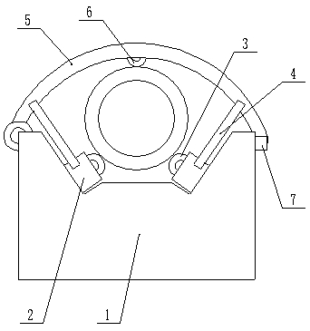
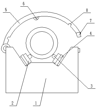
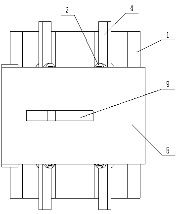
The invention provides a girth welding tool. The girth welding tool comprises a support rack and a clamping mechanism arranged on the support rack, wherein the clamping mechanism comprises a pluralityof support columns, which are arranged obliquely correspondingly on the support rack, and guide wheels, which are mounted rotationally on the support columns; one ends of the support columns are rotationally mounted on the support rack; mounting grooves for mounting the guide wheels are formed in the other ends of the support columns; the guide wheels are mounted on the support columns through rotating shafts; positioning plates are arranged on the supporting columns in the rotation direction of the guide wheels; and a cover plate assembly is arranged at the position, corresponding to the support columns, on the support rack. The girth welding tool can be well applied to the girth welding of a workpiece and well restrict the transverse movement of the workpiece to ensure the welding quality of the workpiece; meanwhile, the workpiece can rotate axially on the girth welding tool, which is convenient for a worker to weld the workpiece quickly; and the support columns and the guide wheelson the support columns can support the workpiece well, and the guide wheels, which are arranged in an rotatable manner, also allow the workpiece to be moved easily on the support columns.

Description

Technical field [0001] The invention belongs to the field of welding tooling, and in particular relates to a circumferential seam welding tooling. Background technique [0002] With the acceleration of my country's industrial modernization, welding technology and welding level have been developed and improved rapidly. Welding has penetrated into all walks of life and all aspects of industrial production. Welding has important and extensive applications in mechanical design and manufacturing departments such as electric power and energy. The level of welding technology and equipment has become a standard for measuring a country’s industrial level. Welding equipment is developing towards mechanization and standardization, and is constantly being improved. The existing welding tooling generally adopts clamping type, which is directly clamped and fixed by clamping blocks. Workpieces are not easy to adjust on the tooling, and it is not easy to adjust the fixed welding position. Worke...

Claims


Application Information

Patent Timeline
Patent Type & Authority Applications(China)
IPC IPC(8): B23K37/047B23K37/053
CPCB23K37/047B23K37/0538
Inventor 崔忠宝崔忠骏李瑞达
Owner 天津市武清区环球锌业有限公司
Learn More