Material conveying device for buildings and using method thereof

A technology for construction and material transportation, which is applied in the direction of transportation and packaging, multi-axis trolleys, trolley accessories, etc. It can solve the problems of inconvenient use for people of different heights, inability to use multiple materials, and inconvenient rapid discharge, etc., to achieve saving Power, save electricity and maintenance costs, the effect of novel structure

Inactive Publication Date: 2019-01-29
淮北辰威科技有限公司
View PDF6 Cites 5 Cited by
  • Summary
  • Abstract
  • Description
  • Claims
  • Application Information

AI Technical Summary

Problems solved by technology

[0002] As the name implies, a material transport vehicle is a vehicle for transporting materials. However, as far as the small construction material transport vehicles currently on the market are concerned, there are still some problems that have always plagued customers, such as complex structures and inconvenient use. , and it is not convenient for people of different heights to use, and at the same time it cannot be used for various materials. For this, the patent application number is CN201720393758. There are deficiencies, one is the lack of a stirring device that can be manually stirred without consuming electric energy and the maintenance cost is small, so that the material is not easy to condense during transportation; the other is the lack of heat dissipation device, so the transporter usually loses energy due to physical exertion during transportation. It feels hot; the third is that it is inconvenient to quickly discharge materials, so it needs to be improved

Method used


Image

  • Material conveying device for buildings and using method thereof
  • Material conveying device for buildings and using method thereof
  • Material conveying device for buildings and using method thereof

Examples


Embodiment Construction

[0022] The following will clearly and completely describe the technical solutions in the embodiments of the present invention with reference to the accompanying drawings in the embodiments of the present invention. Obviously, the described embodiments are only some, not all, embodiments of the present invention. Based on the embodiments of the present invention, all other embodiments obtained by persons of ordinary skill in the art without making creative efforts belong to the protection scope of the present invention.

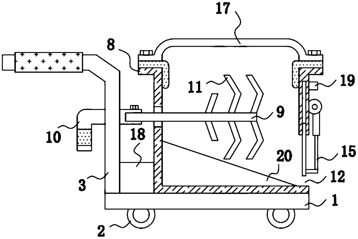
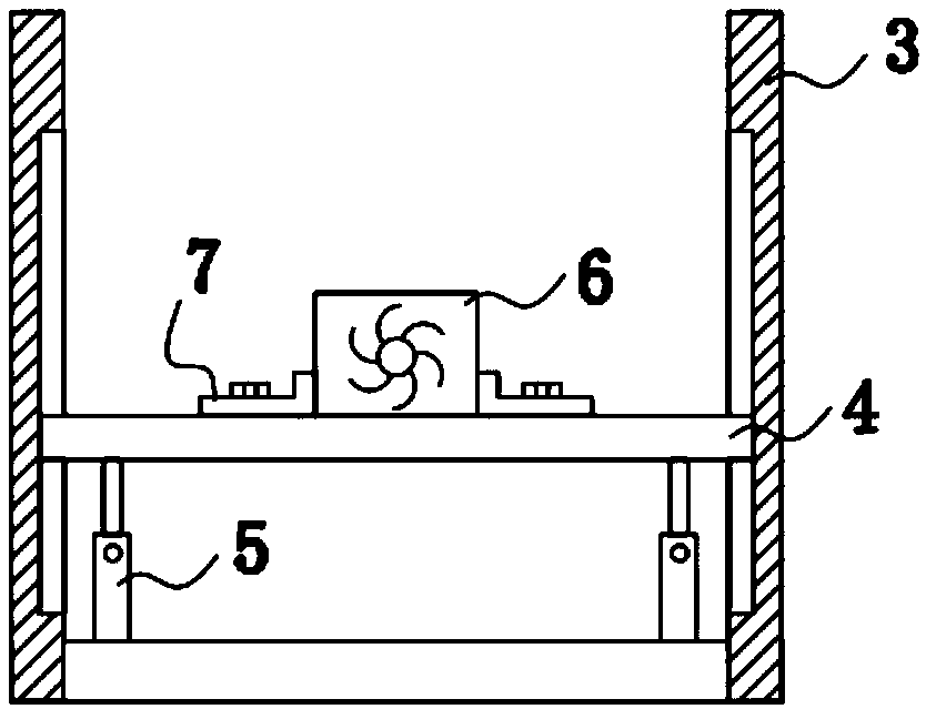
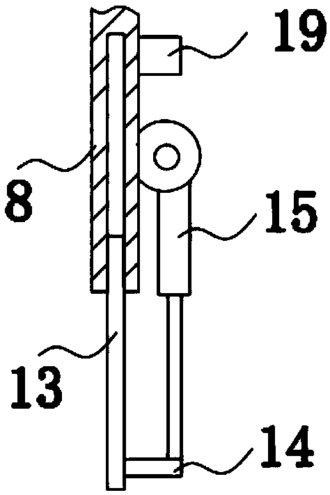
[0023] see Figure 1-5 , the present invention provides a technical solution: a material transport device for construction, including a base 1 and self-locking universal wheels 2 installed at the four corners of the bottom of the base 1, the left and right sides of the rear side of the upper end surface of the base 1 All are welded with integrally formed push rods 3, and a lifting plate 4 is slidably connected between the two push rods 3, and telescopic mechan...


PUM


Abstract

The invention discloses a material conveying device for buildings. The material conveying device comprises a base and self-locking universal wheels installed at four corners at the bottom of the base,wherein integrally formed push rods are welded to the left and right sides of the rear side of the upper end surface of the base, and a lifting plate is slidably connected between the two push rods;and telescopic mechanisms are connected in pairs between the upper end surface of the base and the bottom end surface of the lifting plate, a fan is arranged at the middle position of the upper end ofthe lifting plate, and L-shaped clamping plates abutting against the left and right sides of the fan are arranged in pairs on the upper end surface of the lifting plate. The material conveying deviceuses the self-locking universal wheels to push materials to a material transporting place, tightening screws are used for opening a top cover to pour the materials into a barrel body; in the transportation process, a rotating handle can be rotated to drive a stirring shaft and a stirring branch to rotate by being assisted with of the arrangement of a waterproof bearing, so that the materials areprevented from condensing according to the rotation of the materials, and a motor is not required to drive and rotate, and thus the arrangement can save power and maintenance costs.

Description

technical field [0001] The invention relates to the technical field of construction, in particular to a material transporting device for construction and a method for using the same. Background technique [0002] As the name implies, a material transport vehicle is a vehicle for transporting materials. However, as far as the small construction material transport vehicles currently on the market are concerned, there are still some problems that have always plagued customers, such as complex structures and inconvenient use. , and it is not convenient for people of different heights to use, and at the same time it cannot be used for various materials. For this, the patent application number is CN201720393758. There are deficiencies, one is the lack of a stirring device that can be manually stirred without consuming electric energy and the maintenance cost is small, so that the material is not easy to condense during transportation; the other is the lack of heat dissipation devi...

Claims


Application Information

Patent Timeline
Patent Type & Authority Applications(China)
IPC IPC(8): B62B3/02B62B3/04B62B5/00
Inventor 王晓全钱雷
Owner 淮北辰威科技有限公司
Why Eureka
Try Eureka