Winding machine

A winding machine and revolving technology, which is applied in the direction of conveying filamentous materials, thin material processing, transportation and packaging, etc.

Pending Publication Date: 2019-01-29
OERLIKON TEXTILE GMBH & CO KG
View PDF16 Cites 0 Cited by
  • Summary
  • Abstract
  • Description
  • Claims
  • Application Information

AI Technical Summary

Problems solved by technology

However, this type of four-point mounting requires very precise fitting in terms of assembly

Method used


Image

  • Winding machine
  • Winding machine
  • Winding machine

Examples


Embodiment Construction

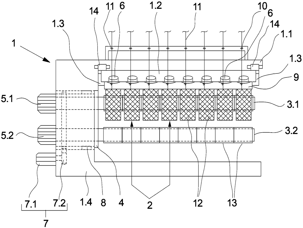
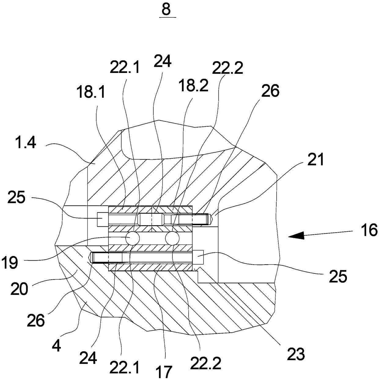
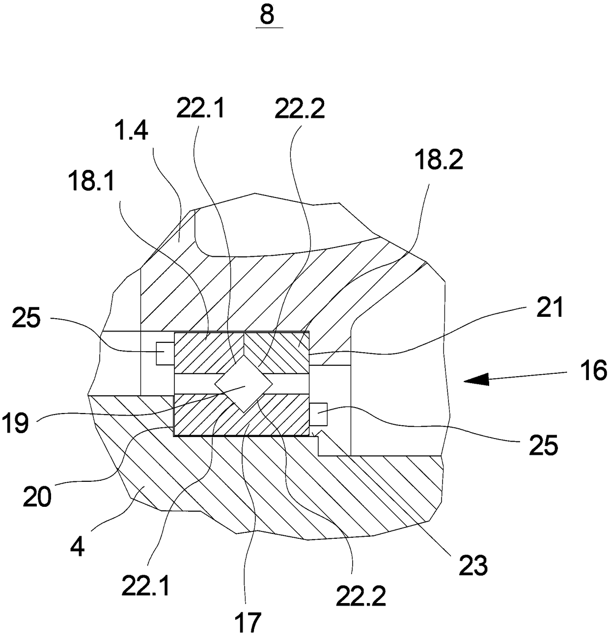
[0021] A first exemplary embodiment of a winder according to the invention is schematically shown in figure 1 side view. The exemplary embodiment of the winding machine has a multi-part machine base frame 1 substantially formed by a machine frame 1.1, a base frame plate 1.2, a roller carrier 1.3 and a rotor housing 1.4. The rotor housing 1 .4 is used to receive the winding turret 4 . The winding turret 4 is mounted rotatably in the rotor housing 1 . 4 in bearing points 8 .

[0022] The winding turret 4 supports two long protruding winding spindles 3.1 and 3.2 on the operating side. The winding spindles 3 . 1 and 3 . 2 are arranged offset from each other by 180° on the winding turret 4 and are coupled in each case to spindle drives 5 . 1 and 5 . 2 arranged on opposite sides of the winding turret 4 . The winding turntable 4 is connected to a turntable drive 7 . The turntable drive 7 is formed in this exemplary embodiment by an electric motor 7.1 held on the rotor housing 1.4...


PUM


Abstract

The invention relates to a winding machine for winding a plurality of threads into coils. For this purpose, the winding machine on two drivable winding spindles and a rotatable spulrevolver, which carries the two winding spindles with a cantilevered free length of at least 1,600 mm and which is mounted in a rotor housing by a rolling bearing. In order to realize the high loads on the winding turret by a passive insensitive and easy to mount storage, according to the invention, an inner ring of the bearing bolted to a bearing flange of the winding turret and screwed an outer ring of the bearingto a support flange of the rotor housing.

Description

technical field [0001] The present invention relates to a winding machine for winding a plurality of yarns to a package. Background technique [0002] A winder of the general type is known, for example, from DE 10060593 A1. [0003] For winding synthetic yarns in the melt spinning process, winders of the type are used in which the yarns are wound simultaneously in parallel on packages of driven winding spindles. The second winding spindle is arranged to enable the melt spinning process to carry out the production of synthetic yarns without interruption. Two winding spindles are held protrudingly on the winding turret. The winding turret is rotatably mounted such that the winding spindles are guided in an alternating manner between a winding area for winding yarn into packages and a changing area for removing full packages. For this purpose, the winding turret in known winding machines is mounted in the rotor housing by means of roller bearings. [0004] In order for a wi...

Claims


Application Information

Patent Timeline
Patent Type & Authority Applications(China)
IPC IPC(8): B65H54/20B65H54/44B65H67/052B65H54/547
CPCB65H54/20B65H54/44B65H54/547B65H67/052B65H2701/31B65H54/72
Inventor D·佩斯特林M·布林克尔
Owner OERLIKON TEXTILE GMBH & CO KG
Why Eureka
Try Eureka