
Bearing inner ring capable of increasing resistance

A technology of bearing inner ring and bearing outer ring, applied in the field of bearing inner ring, can solve the problems of increasing internal stress of bearing ring, difficult bearing assembly, affecting bearing service life, etc., achieving reasonable structure design, reducing use cost, and simplifying The effect of the assembly and disassembly process

Inactive Publication Date: 2019-01-29
慈溪市群兴轴承厂
View PDF0 Cites 0 Cited by
  • Summary
  • Abstract
  • Description
  • Claims
  • Application Information

AI Technical Summary

Problems solved by technology

[0003] The inner ring of the traditional bearing structure is a cylindrical surface, and the shaft is also a cylindrical surface. The two surfaces generally adopt an interference fit to prevent slipping between the inner ring of the bearing and the shaft. The advantage of this structure is that the inner and outer rings are cylindrical and it is more convenient to rotate. , but in the field of heavy construction machinery, bearings often work under very large axial or radial loads. In order to prevent the bearing from deforming under heavy loads and cause slippage between the inner ring of the bearing and the shaft, the bearing generally needs to be used with the shaft The interference fit with a large amount of interference will easily cause the shaft and inner ring to have too much interference, which will make the bearing assembly difficult. Generally, it can only be realized by heating the ring or freezing the shaft. Heating the outer ring is easy to make The tempering of the bearing ring will reduce the surface hardness, which will affect the service life of the bearing. Freezing will easily cause the shaft to rust, resulting in defects in the shaft, and may cause a broken shaft; in addition, too much interference will increase the internal stress of the bearing ring. In severe cases, the ferrule may break

Method used


Image

  • Bearing inner ring capable of increasing resistance

Examples


Embodiment Construction

[0011] The present invention will be further described in detail below in conjunction with the accompanying drawings and embodiments.

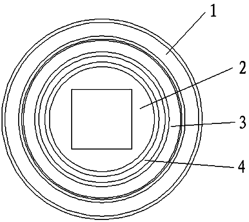
[0012] Such as figure 1 As shown, a bearing inner ring capable of increasing resistance includes a bearing body composed of a bearing outer ring 1, a bearing inner ring 2, a cage 3 and rolling elements 4, and the rolling elements 4 are arranged on the inner surface of the bearing outer ring 1 In the raceway between the outer surface of the bearing inner ring 2 and the outer surface of the bearing inner ring 2, the cage 3 evenly separates a plurality of rolling elements 4, and the inner surface of the bearing inner ring 2 is set in a square structure. The installation surface of the shaft with matching surfaces is set to a square structure, the inner surface of the bearing inner ring 2 and the installation surface of the shaft are clearance fit, and the inner surface of the bearing inner ring 2 is set to a normal shape structure, which can effe...


PUM


Abstract

The invention relates to the technical field of bearings, in particular to a bearing inner ring capable of increasing resistance. The bearing inner ring capable of increasing the resistance comprisesa bearing body composed of a bearing outer ring, the bearing inner ring, a retainer and a plurality of rolling bodies. The rolling bodies are arranged in a roller path between the inner surface of thebearing outer ring and the outer surface of the bearing inner ring. The rolling bodies are evenly spaced from one another by the retainer. The inner surface of the bearing inner ring is of a square structure, and the mounting surface, matched with the inner surface of the bearing inner ring, of a shaft is also of a square structure. The inner surface of the bearing inner ring is in clearance fitwith the mounting surface of the shaft. The bearing inner ring is reasonable in structural design; the inner surface of the bearing inner ring is of the square structure, so that the resistance of thebearing inner ring is effectively increased, and slipping between the shaft and the bearing inner ring under the effect of a large load is avoided; and meanwhile, the bearing inner ring and the shaftare in clearance fit, so that the disassembling process of a bearing is simplified, and the usage cost of the bearing is reduced.

Description

technical field [0001] The invention relates to the technical field of bearings, in particular to a bearing inner ring capable of increasing resistance. Background technique [0002] In mechanical design, the cooperation between bearings, shafts and bearing housings generally adopts the interference fit according to the cooperation of moving parts, and the principle of clearance fit is adopted for the cooperation of stationary parts, so as to ensure the effective combination of moving parts and bearing mating surfaces to ensure the normal transmission of motion. [0003] The inner ring of the traditional bearing structure is a cylindrical surface, and the shaft is also a cylindrical surface. The two surfaces generally adopt an interference fit to prevent slipping between the inner ring of the bearing and the shaft. The advantage of this structure is that the inner and outer rings are cylindrical and it is more convenient to rotate. , but in the field of heavy construction ma...

Claims


Application Information

Patent Timeline
Patent Type & Authority Applications(China)
IPC IPC(8): F16C33/58
CPCF16C33/58
Inventor 史亦群
Owner 慈溪市群兴轴承厂
Learn More