
Magnet valve and gas furnace thereof

A magnet valve and air outlet technology, which is used in heating fuel, household stove/stove, gaseous heating fuel, etc., can solve the problem that the operator cannot identify the rotation position of the adjustment rod, the body is fat and heavy, and the size of the magnet valve is large.

Inactive Publication Date: 2019-01-29
中山亨泰燃气具有限公司
View PDF0 Cites 0 Cited by
  • Summary
  • Abstract
  • Description
  • Claims
  • Application Information

AI Technical Summary

Problems solved by technology

[0003] 1. The adjustment rod of the magnet valve directly twists the valve core to adjust the firepower and switch. If the operator fails to reset the adjustment rod (closed state) and forcefully loads the gas cylinder, the parts of the magnet valve will be damaged, and even the gas cylinder may explode. , the reason is that the operator cannot recognize the rotation position of the adjustment lever
[0004] 2. When the adjustment lever is turned, it can only realize the function of firing and closing the fire, and there is no firepower adjustment and accurate positioning of the firepower structure
[0005] 3. In the existing magnet valve structure, since the axes of the air inlet and the air outlet are parallel to each other, that is, the axes of the air inlet and the air outlet are not on the same axis, therefore, the inner space of the magnet valve cavity needs to be designed with enough space for accommodation, so that The overall volume of the magnet valve is too large, which takes up a lot of space on the stove, resulting in a large shape of the stove, which is fat and heavy, which is not easy to carry
[0006] 4. The air outlet part of the magnet valve is set at the bottom of the magnet valve cavity or near the bottom. In case of failure of the air guide tube, it is not easy to disassemble

Method used


Image

  • Magnet valve and gas furnace thereof
  • Magnet valve and gas furnace thereof
  • Magnet valve and gas furnace thereof

Examples


Embodiment Construction

[0026] The specific embodiments of the present invention will be further described below in conjunction with the accompanying drawings. It should be noted here that the descriptions of these embodiments are used to help understand the present invention, but are not intended to limit the present invention. In addition, the technical features involved in the various embodiments of the present invention described below may be combined with each other as long as they do not constitute a conflict with each other.

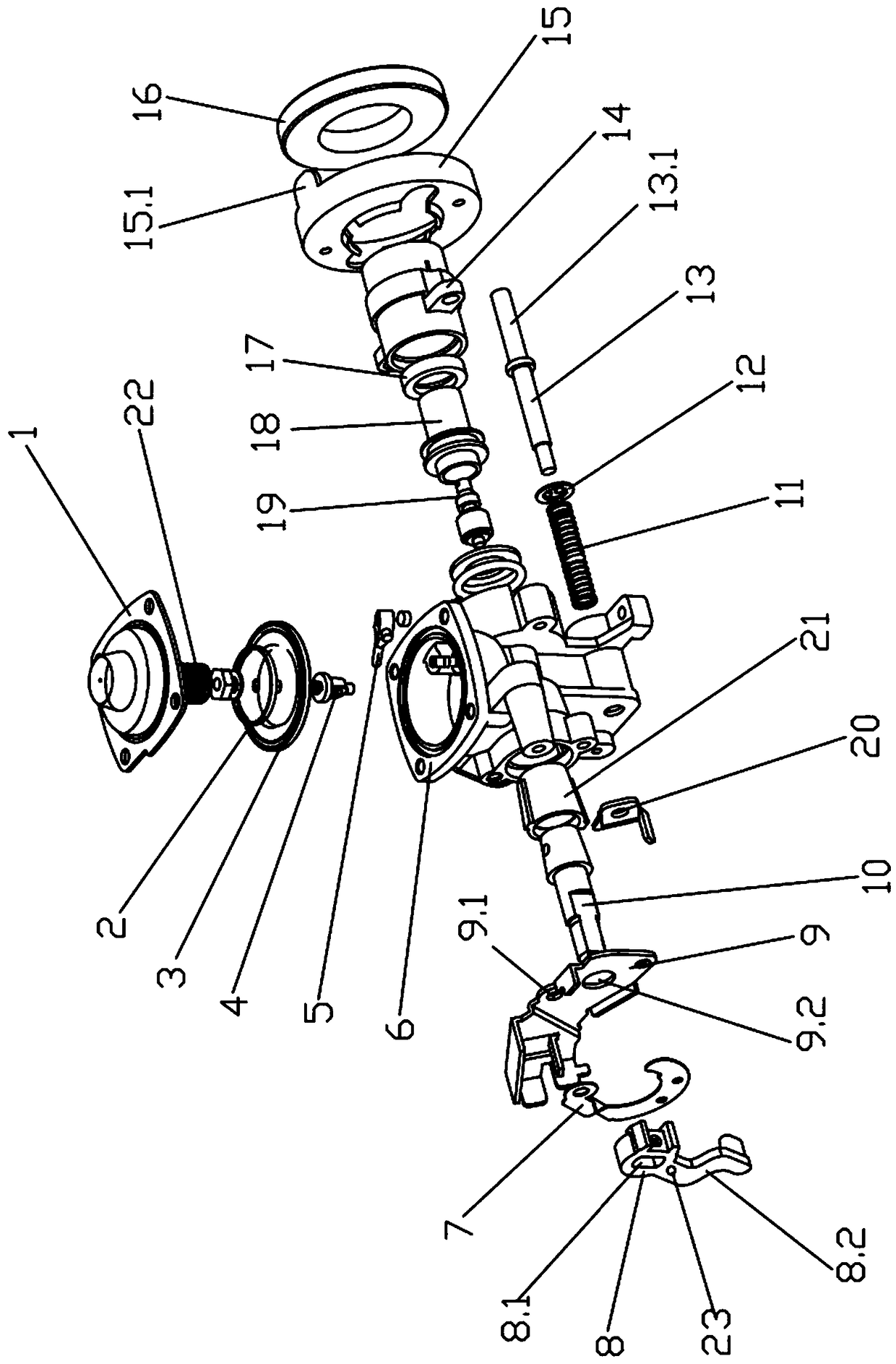
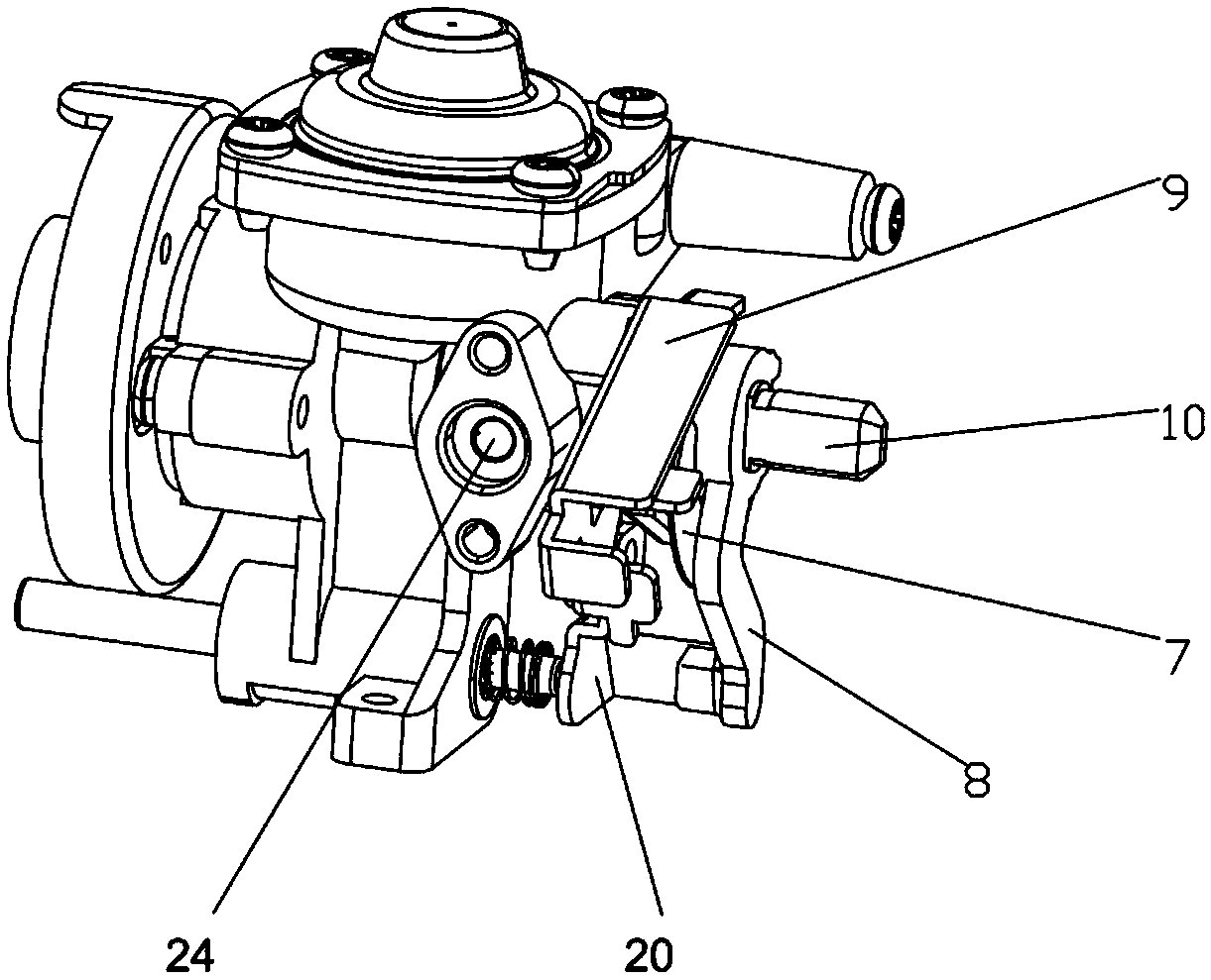
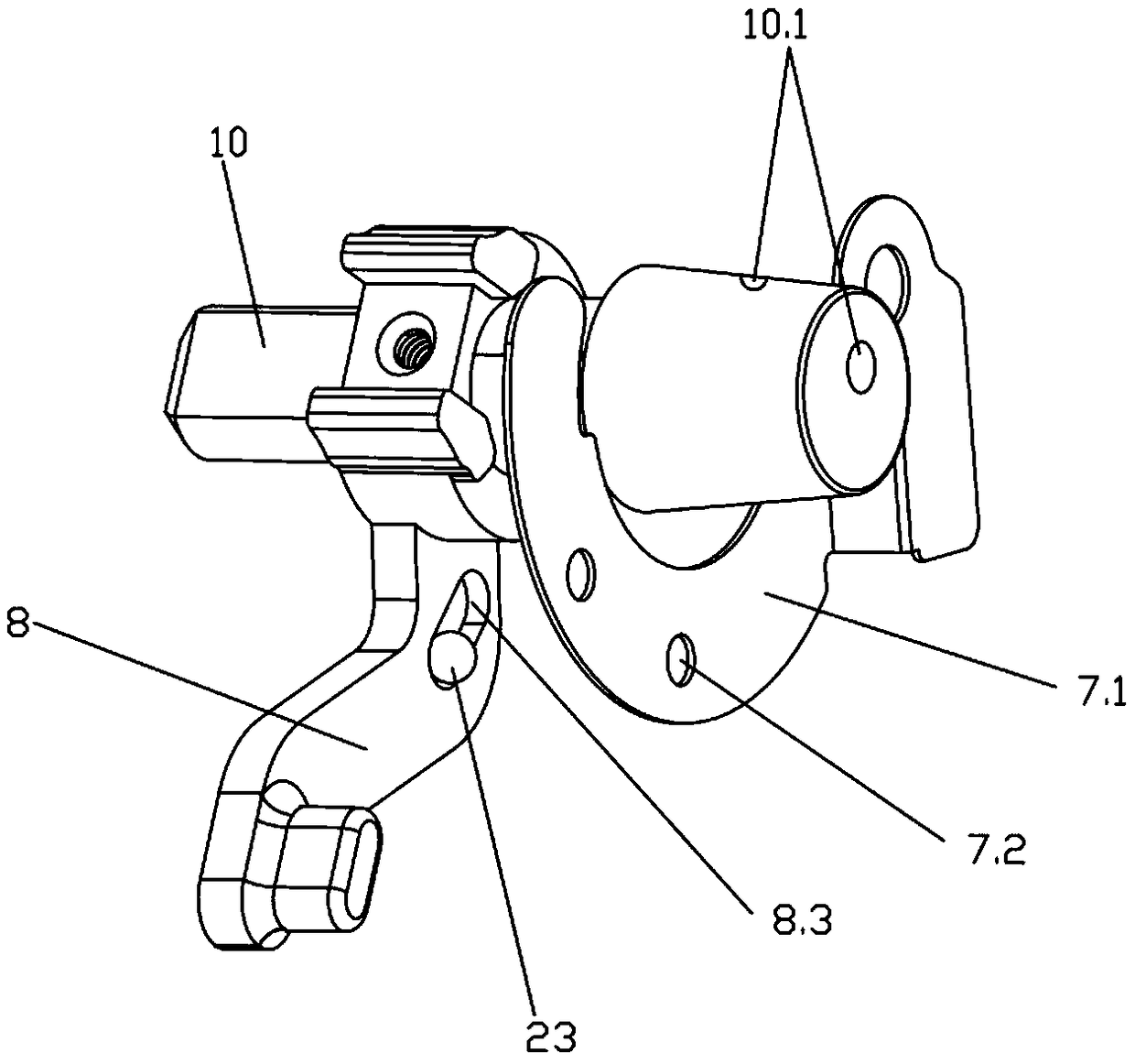
[0027] like Figure 1 to Figure 4 As shown, the main body of the magnet valve is the cavity 6, which is made of zinc alloy casting, which is not easy to leak and can effectively ensure air tightness. The cavity 6 is provided with three communicating channels, which are the air inlet channel 6.1, the air outlet channel 6.2 and the pressure relief channel 6.3, and the air outlet channel 6.3 is a tapered cavity.

[0028] The air intake channel 6.1 of the cavity 6 is equip...


PUM


Abstract

The invention discloses a magnet valve and a g as furnace thereof. A cavity of the magnet valve is provided with an air inlet channel and an air outlet channel, a sleeve ring is assembled in the air outlet channel, an insertion end of an adjusting rod is sleeved with the sleeve ring, the rotary knob end of the adjusting rod is sleeved with a sounding part, a groove is formed in the inner side of the sounding part, and the groove can contain a rolling impact part; a swing prompt part is arranged between the sounding part and a port of the air outlet channel, when the rotary knob adjusting rod drives the sounding part to rotate, the impact part in the groove of the sounding part makes contact with the prompt part, prompt sounds are generated, the fire function of the gas furnace is promoted,the adjusting position of the adjusting rod is distinguished by means of sounds, and operation accuracy positioning can be achieved; meanwhile, due to the fact that the adjusting rod can be recognized, when the adjusting rod is reset, the phenomenon that a gas bottle is forced to connect with the magnet valve by accident is avoided, the phenomenon that the magnet valve gas bottle ejector rod partis damaged, and a gas bottle is exploded is avoided, and the safety of the gas furnace is improved.

Description

technical field [0001] The invention belongs to gas equipment and ignition control parts thereof, in particular to a magnet valve and a gas furnace using the magnet valve for ignition and combustion. Background technique [0002] With the improvement of living standards, small and portable gas stoves are favored by people, and they are necessary stoves for family dinners, outdoor cooking, and outdoor barbecues. The magnet valve of existing gas furnace has the following disadvantages: [0003] 1. The adjustment rod of the magnet valve directly twists the valve core to adjust the firepower and switch. If the operator fails to reset the adjustment rod (closed state) and forcefully loads the gas cylinder, the parts of the magnet valve will be damaged, and even the gas cylinder may explode. , the reason is that the operator cannot recognize the rotation position of the adjustment lever. [0004] 2. When the adjustment lever is turned, only the function of firing and shutting of...

Claims


Application Information

Patent Timeline
IPC IPC(8): F24C3/10F24C3/12
CPCF24C3/10F24C3/122
Inventor 区志伟
Owner 中山亨泰燃气具有限公司
Learn More