A light field measurement calibration method and calibration system

A calibration method and a technology for calibrating objects, applied in the field of optics, can solve problems such as the inability to measure the depth of object space, and achieve the effect of easy implementation and high precision

Active Publication Date: 2020-09-25
SHENZHEN UNIV
View PDF6 Cites 0 Cited by
  • Summary
  • Abstract
  • Description
  • Claims
  • Application Information

AI Technical Summary

Problems solved by technology

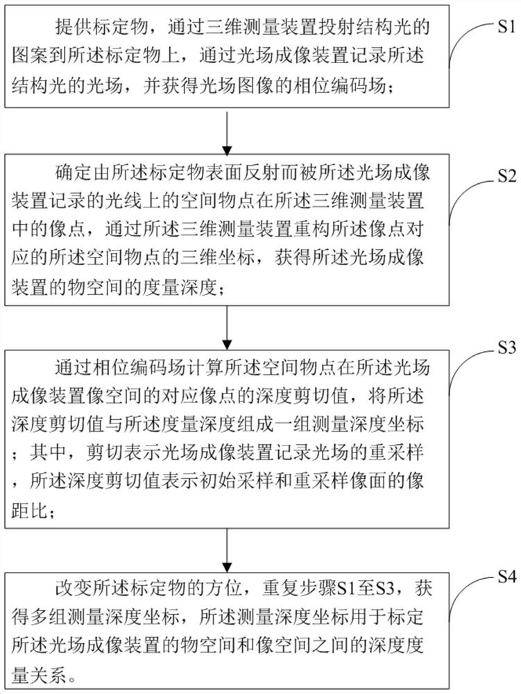
[0003] The purpose of the present invention is to provide a light field measurement calibration method, aiming to solve the technical problem that the depth measurement of the object space cannot be carried out in the traditional light field imaging technology

Method used


Image

  • A light field measurement calibration method and calibration system
  • A light field measurement calibration method and calibration system
  • A light field measurement calibration method and calibration system

Examples


Embodiment Construction

[0024] In order to make the object, technical solution and advantages of the present invention clearer, the present invention will be further described in detail below in conjunction with the accompanying drawings and embodiments. It should be understood that the specific embodiments described here are only used to explain the present invention, not to limit the present invention.

[0025] It should be noted that when a component is referred to as being “fixed on” or “disposed on” another component, it may be directly or indirectly located on the other component. When an element is referred to as being "connected to" another element, it can be directly or indirectly connected to the other element. The terms "upper", "lower", "left", "right", "front", "rear", "vertical", "horizontal", "top", "bottom", "inner", "outer", etc. The indicated orientation or position is based on the orientation or position shown in the drawings, and is only for convenience of description, and should...


PUM


Abstract

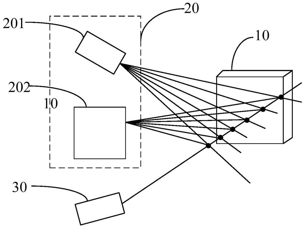
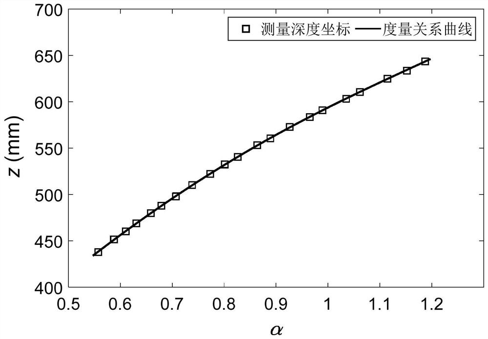
The invention is applicable to the technical field of optics, and provides a light field measurement calibration method comprising the steps: a calibration object is provided, the pattern of the structured light is projected onto the calibration object through a three-dimensional measuring device, and the light field of the structured light is recorded through a light field imaging device and a phase coding field is obtained; the three-dimensional coordinates of the spatial object points are reconstructed by the three-dimensional measuring device so as to obtain the measurement depth of the object space of the light field imaging device; the depth shear values of the image points of the spatial object points in the image space of the light field imaging device are calculated by the phase coding field, and the depth shear values and the measurement depth form a set of measurement depth coordinates; and the position of the calibration object is changed and the above steps are repeated toobtain multiple sets of measurement depth coordinates for calibrating the object space and image space depth measurement relationship of the light field imaging device. The depth of the object spacecan be accurately determined by the depth of the image space based on the measurement relationship so that light field imaging is enabled to have the function of image space depth perception and the function of object space depth measurement.

Description

technical field [0001] The invention belongs to the field of optical technology, and in particular relates to a light field measurement calibration method and a calibration system. Background technique [0002] Light field imaging is a novel imaging method and technology. Compared with traditional imaging that can only record the light intensity of light, light field imaging can simultaneously record the intensity and direction information of light, expanding the light recording dimension from two-dimensional to four-dimensional, breaking through the performance limitations of traditional imaging. For example, digital refocusing can be realized by cutting light field data; multi-view imaging can be realized by selecting sub-images. These imaging properties contain scene-related depth cues, making light field imaging capable of depth estimation. However, this depth estimation is only depth perception in image space rather than depth measurement in object space. Depth measu...

Claims


Application Information

Patent Timeline
Patent Type & Authority Patents(China)
IPC IPC(8): G01B11/25
CPCG01B11/2504
Inventor 刘晓利彭翔蔡泽伟
Owner SHENZHEN UNIV
Why Eureka
Try Eureka