Laser processing apparatus, laser processing method, and correction data generation method

A laser processing and laser technology, applied in the direction of optical devices, measuring devices, laser welding equipment, etc., can solve problems such as difficult keyhole depth measurement, and achieve the effect of accurate depth measurement

Pending Publication Date: 2020-11-17
PANASONIC INTELLECTUAL PROPERTY MANAGEMENT CO LTD
View PDF1 Cites 0 Cited by
  • Summary
  • Abstract
  • Description
  • Claims
  • Application Information

AI Technical Summary

Problems solved by technology

Therefore, it is difficult to accurately measure the depth of the keyhole

Method used


Image

  • Laser processing apparatus, laser processing method, and correction data generation method
  • Laser processing apparatus, laser processing method, and correction data generation method
  • Laser processing apparatus, laser processing method, and correction data generation method

Examples


Embodiment approach 1

[0127] (Embodiment 1) Item 1

[0128]

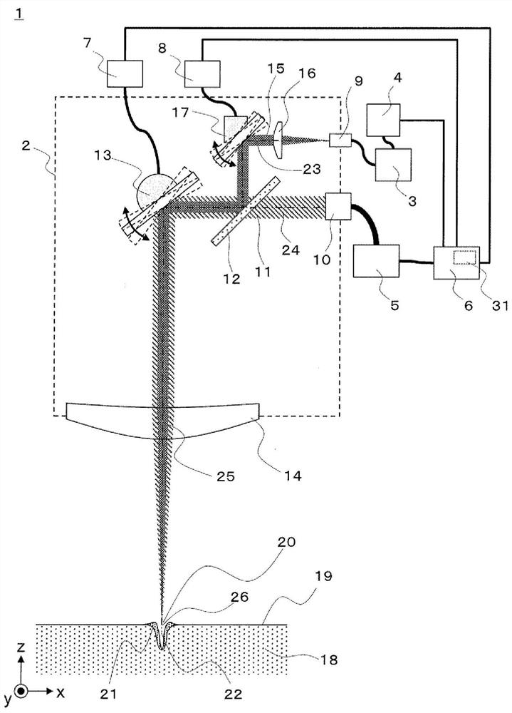
[0129] figure 1 It is a figure which shows the structure of the laser processing apparatus 1 in Embodiment 1 of this invention. The laser processing device 1 is composed of a processing head 2 , an optical interferometer 3 , a measurement processing unit 4 , a laser oscillator 5 , and a control unit 6 . Optical interferometer 3 emits measurement light 15 for OCT measurement, and laser oscillator 5 oscillates processing laser light 11 for laser processing. The measurement light 15 is input to the processing head 2 from the measurement light introduction port 9 , and the processing laser light 11 oscillated by the laser oscillator 5 is input to the processing head 2 from the processing light introduction port 10 .

[0130] The processing laser light 11 introduced from the processing light inlet 10 passes through the dichroic mirror 12 , is reflected by the first reflection mirror 13 , passes through the lens 14 , and is focused on the p...

Embodiment approach 2

[0247] Embodiments of the present disclosure will be described below with reference to the drawings. In addition, in each figure, the same code|symbol is attached|subjected to the common component, and their description is abbreviate|omitted suitably. Matters not described are the same as those in Embodiment 1.

[0248] [Structure of laser processing device]

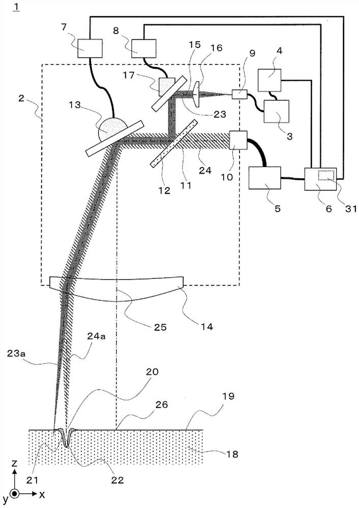
[0249] use Figure 16 The configuration of the laser processing apparatus 1 according to the embodiment of the present disclosure will be described. Figure 16 It is a figure which schematically shows the structure of the laser processing apparatus 1 of this embodiment.

[0250] The laser processing device 1 includes a processing head 2 , an optical interferometer 3 , a measurement processing unit 4 , a laser oscillator 5 , a control unit 6 , a first driver 7 , a second driver 8 , and a third driver 41 .

[0251] The optical interferometer 3 emits measurement light 15 for OCT measurement. The emitted measurement lig...

Deformed example 1

[0463] In the embodiment, in order to change the direction of the optical axis of the measurement light 15 , the case of using the second mirror 17 as a galvanometer mirror was described as an example, but the present disclosure is not limited thereto.

[0464] The second mirror used in the laser processing device 1 may be, for example, disposed between the measurement light inlet 9 and the dichroic mirror 12 and capable of changing the direction of the optical axis of the measurement light 15 under the control of the control unit 6 .

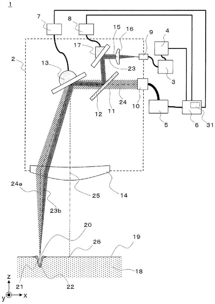
[0465] The second reflection mirror 35 of this structure is shown in Figure 36 . Figure 36 It schematically shows the laser processing device 1 using the second mirror 35 .

[0466] Figure 36 The laser processing device shown in 1 replaces the Figure 16 The second reflection mirror 17 shown by etc. has a second reflection mirror 35 , and further has a moving table 36 and a table driver 37 . in addition, Figure 36 The laser processing ...


PUM


Abstract

The invention provides a laser processing apparatus, a laser processing method, and a correction data generation method, which can accurately measure the depth of a key hole. A laser processing apparatus includes: a laser oscillator configured to oscillate a laser beam for processing at a processing point to be processed on a surface of a workpiece; an optical interferometer that emits measurementlight to the processing point and generates an optical interference intensity signal based on interference generated by an optical path difference between the measurement light reflected at the processing point and the reference light; a first mirror that changes the direction of advancement of the machining laser light and the measurement light; a second mirror that changes the angle of incidence of the measurement light to the first mirror; a lens that focuses the machining laser light and the measurement light to a machining point; a memory for storing the corrected processing data; a control unit that controls the laser oscillator, the first mirror, and the second mirror on the basis of the corrected processing data; and a measurement processing unit that derives, on the basis of thelight interference intensity signal, the depth of the keyhole generated at the machining point by the machining laser light.

Description

technical field [0001] The present invention relates to a laser processing device, a laser processing method, and a correction data generation method for processing an object to be welded. Background technique [0002] As a conventional laser processing device, a device using OCT (Optical Coherence Tomography, Optical Coherence Tomography) technology that visualizes the internal structure of a sample using an optical interferometer has been proposed to measure the laser-based metal processing. The depth of the keyhole produced in (refer to Patent Document 1). Figure 38 It is a figure which shows the structure of the conventional laser processing apparatus described in patent document 1. [0003] exist Figure 38 In the process, the laser light 107 for processing and the measurement light 105 are introduced into the welding joint 108 . In particular, the measurement light 105 is arranged to have a coaxial structure sharing an optical axis with the processing laser light 107...

Claims


Application Information

Patent Timeline
Patent Type & Authority Applications(China)
IPC IPC(8): B23K26/36B23K26/382B23K26/70B23K26/064G01B11/22
CPCB23K26/36B23K26/382B23K26/702B23K26/064B23K26/0643B23K26/0648G01B11/22B23K26/082B23K26/032B23K26/21B23K26/062B23K26/50
Inventor 武智洋平横山润浦岛毅吏
Owner PANASONIC INTELLECTUAL PROPERTY MANAGEMENT CO LTD
Why Eureka
Try Eureka