
Dynamic leaching system and method

A leaching and dynamic technology, applied in the direction of measuring devices, instruments, scientific instruments, etc., can solve the problems of inconsistency in leaching indicators, difficulty in controlling on-site stabilization/curing quality, differences, etc., to achieve easy operation, high practical application value, Equipment composed of simple effects

Inactive Publication Date: 2019-01-29
HUNAN JUNXIN ENVIRONMENTAL PROTECTION CO LTD
View PDF6 Cites 2 Cited by
  • Summary
  • Abstract
  • Description
  • Claims
  • Application Information

AI Technical Summary

Problems solved by technology

[0003] At present, there are many leaching toxicity test methods for solid waste such as fly ash. These methods can evaluate the potential leaching of pollutants in the environment, but different methods may lead to significantly different conclusions
At present, the common problems are that because the site conditions and environment are affected by the weather, after the leaching experiment is carried out in the laboratory, due to the difference between the laboratory leaching environment and the on-site environment, the laboratory results do not match the actual leaching indicators on site. Difficult to control on-site stabilization / curing quality

Method used


Image

  • Dynamic leaching system and method

Examples


Embodiment 1

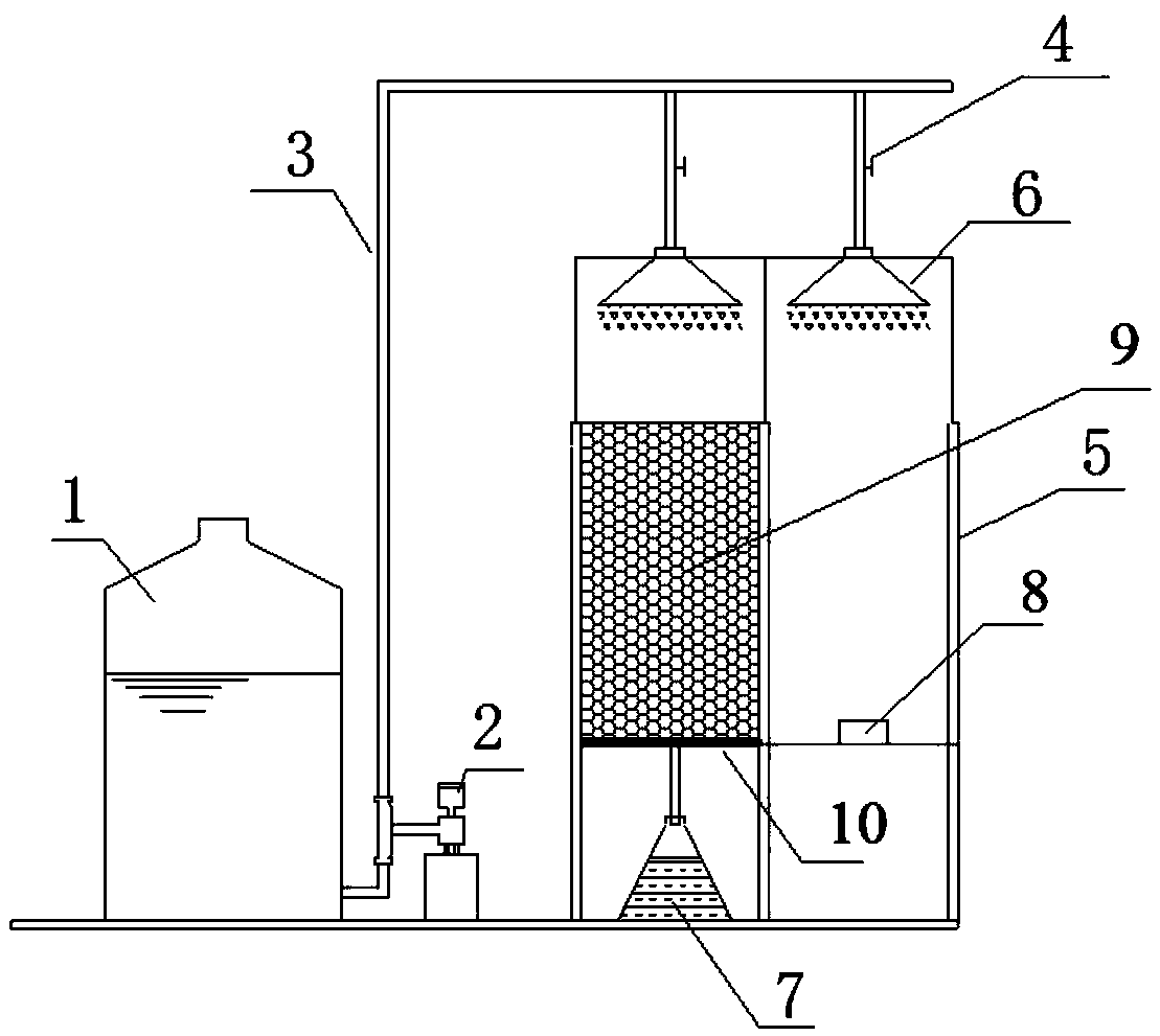
[0032] A dynamic leaching system of the present invention can realize the dynamic leaching of waste incineration fly ash in a simulated field environment, such as figure 1 As shown, it includes a container 1 for containing the leaching solvent, a metering pump 2, a delivery pipeline 3, a timer 4, two columnar containers 5 with the same specifications, and corresponding nozzles 6 for spraying the solution in the two columnar containers 5 ( That is, the nozzle 6) for spraying the leaching solvent in each columnar container 5), the collecting container 7 and the rain gauge 8, and one end (first end) of the delivery pipe 3 is connected (communicated) with the solvent outlet of the container 1 containing the solvent. The output port, and a metering pump 2 for transporting the leaching solvent is provided on the delivery pipeline 3 near one end of the container 1, and the other end (second end) is sealed, and the delivery pipeline 3 is on the other end (second end) near the delivery ...

Embodiment 2

[0047] A kind of dynamic leaching method of the present invention, adopts such as figure 1 The described system carries out leaching, comprises the steps:

[0048] (1) Prepare the leaching solvent in the container 1 according to the water quality of the actual local rainfall; and fill the sample 9 to be leached into a columnar container 5 to form a filling layer. Place the rain gauge 8.

[0049] (2) Start the metering pump 2, deliver the leaching solvent to the two nozzles 6 and evenly spray the leaching solvent into the two columnar containers 5, so that the leaching solvent is synchronized and evenly sprayed on the sample 9 to be leached and the rain gauge 8; specifically, For the metering pump 2, the leaching solvent is transported to each bifurcated branch pipeline through the delivery pipeline 3, and sprayed in each columnar container 5 through each nozzle 6 communicated with each bifurcated branch pipeline, and the spraying situation of each nozzle 6 includes The spray...


PUM

PropertyMeasurementUnit
Thicknessaaaaaaaaaa
Particle sizeaaaaaaaaaa
Thicknessaaaaaaaaaa

Abstract

The invention discloses a dynamic leaching system. The dynamic leaching system comprises a container for containing a solvent, a metering pump, a conveying pipeline, at least two columnar containers,spray heads for spraying a leaching solvent into respective columnar containers, a collection container and rain gauges. One end of the conveying pipeline communicates with the container; the meteringpump is arranged on the conveying pipeline close to one end of the container; at least two branch pipelines are arranged at the other end of the conveying pipeline; each branch pipeline communicateswith one corresponding spray head; one columnar container is arranged below each spray head; one rain gauge is arranged in a cavity of one corresponding columnar container, and other columnar containers are used for containing to-be-leached samples and are provided with water outlets in the bottom walls; a filter is arranged above the bottom walls; and the obtained lixivium flows into the collection container through the water outlets. The invention further discloses a dynamic leaching method. The dynamic leaching system is simple in structure and can simulate toxicity dynamic leaching on solid waste, such as fly ash, in an on-site environment; and the method is simple to operate, wide in application and high in simulation effect.

Description

technical field [0001] The invention relates to the field of solid waste leaching analysis, in particular to a dynamic leaching system and method. Background technique [0002] In recent years, China's municipal solid waste has been increasing at an annual rate of 8%, and China has become one of the countries with the heaviest burden of waste in the world. Our country usually adopts the method of incineration to deal with municipal solid waste. After the waste is incinerated, the volume of the waste can be reduced by 90%, and the weight can be reduced by 70%, which effectively reduces the area occupied by the waste pile. However, during the incineration of domestic waste, a large amount of fly ash (accounting for about 3% to 5% of the total waste incinerated) is produced. Fly ash is the residue collected in the flue gas purification system and heat recovery system. It is a substance produced by condensation or chemical reaction of small particles of ash blown up by combusti...

Claims


Application Information

Patent Timeline
IPC IPC(8): G01N33/00
CPCG01N33/00
Inventor 李林陈杰李求伟伍兵张大春杨振秋王威李方志唐松乔夏良张乐
Owner HUNAN JUNXIN ENVIRONMENTAL PROTECTION CO LTD
Learn More