Motor control mode fault detection method and device

A technology of motor control and fault detection, applied in the direction of motor control, control system, electrical components, etc., can solve the problem of machine explosion and other problems, achieve the effect of improving accuracy and avoiding catastrophic consequences

Active Publication Date: 2019-01-29
SHENZHEN AUTEL INTELLIGENT AVIATION TECH CO LTD
View PDF4 Cites 3 Cited by
  • Summary
  • Abstract
  • Description
  • Claims
  • Application Information

AI Technical Summary

Problems solved by technology

However, if there is a problem with the sensor, it will be catastrophic for the motor control, and the whole machine will definitely explode

Method used


Image

  • Motor control mode fault detection method and device
  • Motor control mode fault detection method and device
  • Motor control mode fault detection method and device

Examples


Embodiment 1

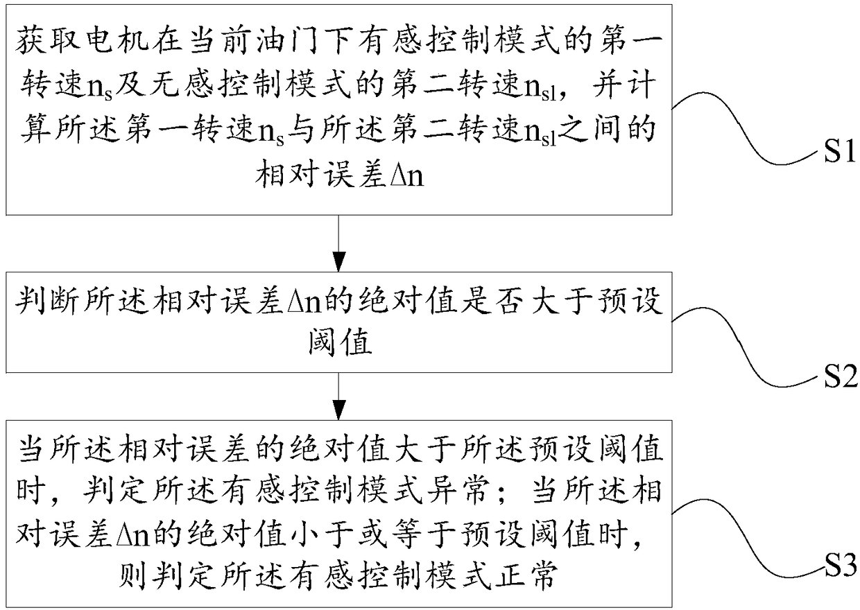
[0045] An embodiment of the present invention provides a motor control mode fault detection method, such as figure 1 As shown, the motor control mode fault detection method mainly includes the following steps:

[0046] Step S1: Obtain the first speed n of the electric motor in the sensory control mode under the current throttle s And the second speed n of the non-inductive control mode sl , and calculate the first rotational speed n s with the second speed n sl The relative error Δn between;

[0047] Step S2: judging whether the absolute value of the relative error Δn is greater than a preset threshold;

[0048]Step S3: When the absolute value of the relative error Δn is greater than the preset threshold, it is determined that the sensory control mode of the motor is abnormal; when the absolute value of the relative error Δn is less than or equal to the preset threshold, it is determined that the sensory control mode of the motor is abnormal The control mode is normal.

...

Embodiment 2

[0093] An embodiment of the present invention provides a motor control mode fault detection device, such as Figure 4 As shown, the motor control mode fault detection device mainly includes: a relative error acquisition unit 1, an error judgment unit 2, an abnormal mode judgment unit 3, and the like.

[0094] Wherein, the above-mentioned relative error acquisition unit 1 is used to acquire the first rotational speed n of the electric motor in the sensed control mode under the current throttle. s And the second speed n of the non-inductive control mode sl , and calculate the first rotational speed n s with the second speed n sl The relative error Δn between them; the error judging unit 2 is used to judge whether the absolute value of the relative error Δn is greater than a preset threshold; the abnormal mode judging unit 3 is used to determine whether the absolute value of the relative error Δn is greater than the preset threshold The sensory control mode of the motor is abn...

Embodiment 3

[0118] Figure 6A and Figure 6B It is a schematic diagram of the hardware structure of the motor control mode fault detection component implementing the motor control mode fault detection method provided by the embodiment of the present invention, as shown in Figure 6A and Figure 6B As shown, the motor control mode fault detection component includes one or more processors 610 and memory 620, Figure 6A and Figure 6B A processor 610 is taken as an example.

[0119] The motor control mode fault detection component implementing the motor control mode fault detection method may further include: an input device 630 and an output device 640 .

[0120] Processor 610, memory 620, input device 630, and output device 640 may be connected by bus or other means, Figure 6A and Figure 6B Take connection via bus as an example.

[0121] The processor 610 may be a central processing unit (Central Processing Unit, CPU). The processor 610 may also be other general-purpose processor...


PUM


Abstract

The invention provides a motor control mode fault detection method and device. The motor control mode fault detection method comprises the steps of obtaining first rotating speed ns of an inductive control mode and second rotating speed nsl of a non-inductive control mode under the current throttle of a motor, and calculating a relative error [delta]n between the first rotating speed ns and the second rotating speed nsl; judging whether an absolute value of the relative error [delta]n is greater than a preset threshold or not; if the absolute value of the relative error [delta]n is greater than the preset threshold, determining that the inductive control mode is abnormal; and if the absolute value of the relative error [delta]n is less than or equal to the preset threshold, determining that the inductive control mode is normal. According to the embodiment of the invention, the accuracy of motor control mode fault detection can be improved, and the motor control mode can be switched into the non-inductive control mode more timely and effectively in the case that the inductive control mode fails, thereby avoiding disastrous consequences brought about by motor control errors caused bysensor failure.

Description

technical field [0001] The invention relates to the technical field of motor control, in particular to a motor control mode fault detection method and device. Background technique [0002] The safety and reliability of motor equipment, especially those used in unmanned aerial vehicles (especially industrial drones), is very important. For motor control, the sensory control mode is adopted, that is, there are sensors (magnetic encoding, linear / switching Hall, etc.) to obtain speed and position information. However, if there is a problem with the sensor, it will be disastrous for the motor control, and the whole machine will definitely explode. Therefore, how to detect whether the sensory control mode of the motor fails is particularly important. [0003] Therefore, when the sensor used in the sensory control mode fails, how to effectively detect and judge the fault situation, and promptly switch the motor control from the currently used sensory control mode to the sensorles...

Claims


Application Information

Patent Timeline
IPC IPC(8): H02P29/024H02P29/028
CPCH02P29/024H02P29/028H02P29/0241H02P29/032
Inventor 陈毅东
Owner SHENZHEN AUTEL INTELLIGENT AVIATION TECH CO LTD
Why Eureka
Try Eureka