
Unmanned aerial vehicle with foldable landing gear

A technology of unmanned aerial vehicles and landing gear, which is applied in the field of unmanned aerial vehicles, can solve the problems of affecting the flight range, complicated control methods, large wind resistance of unmanned aerial vehicles, etc., and achieve the effects of simple structure, extended service life and good use effect

Inactive Publication Date: 2019-02-01
深圳市富裕泰贸易有限公司
View PDF5 Cites 4 Cited by
  • Summary
  • Abstract
  • Description
  • Claims
  • Application Information

AI Technical Summary

Problems solved by technology

[0002] At present, there are two types of traditional drones, one is unmanned drones with landing gear, and the other is unmanned drones without landing gear; the landing gear on drones with landing gear rarely has a stacking function. UAVs that do not have a stackable landing gear have a large wind resistance during flight, which affects the range; even if some UAVs have a stackable landing gear, it will increase infinitely due to the complexity of the control method of the landing gear. Man-machine research and development and production costs; traditional UAVs with landing gear generally have two control methods for the landing gear: one is to control the hydraulic pump installed on the body through the motor, and then control the three landing gears through hydraulic pressure. The other is to control the folding of the three landing gears through at least two servo motors; this traditional way of stacking the landing gear also increases the R&D and production costs of the UAV, thus affecting the UAV being used. The progress of widespread application, which in turn affects the economic benefits of related enterprises

Method used


Image

  • Unmanned aerial vehicle with foldable landing gear
  • Unmanned aerial vehicle with foldable landing gear
  • Unmanned aerial vehicle with foldable landing gear

Examples


Embodiment Construction

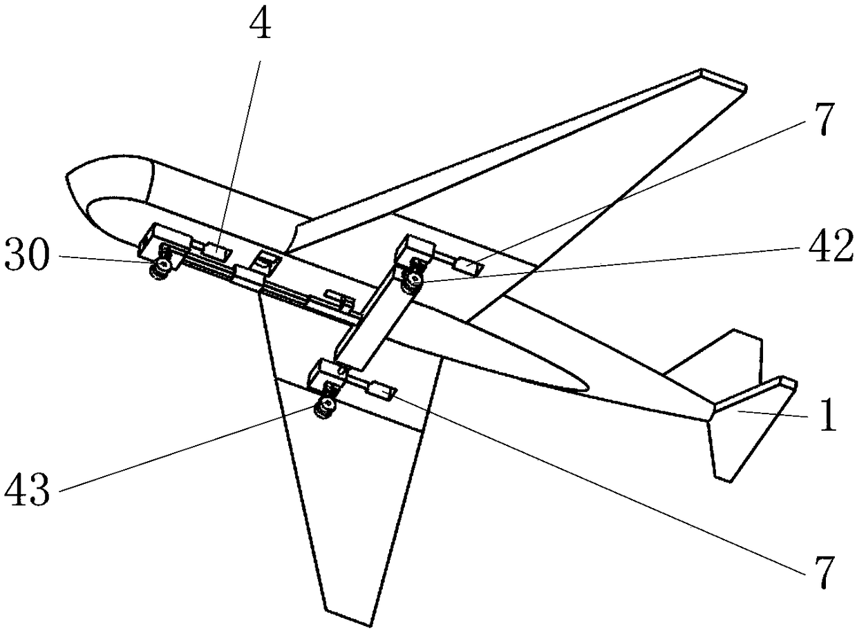
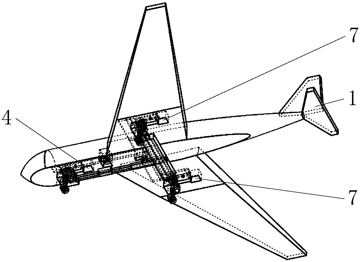
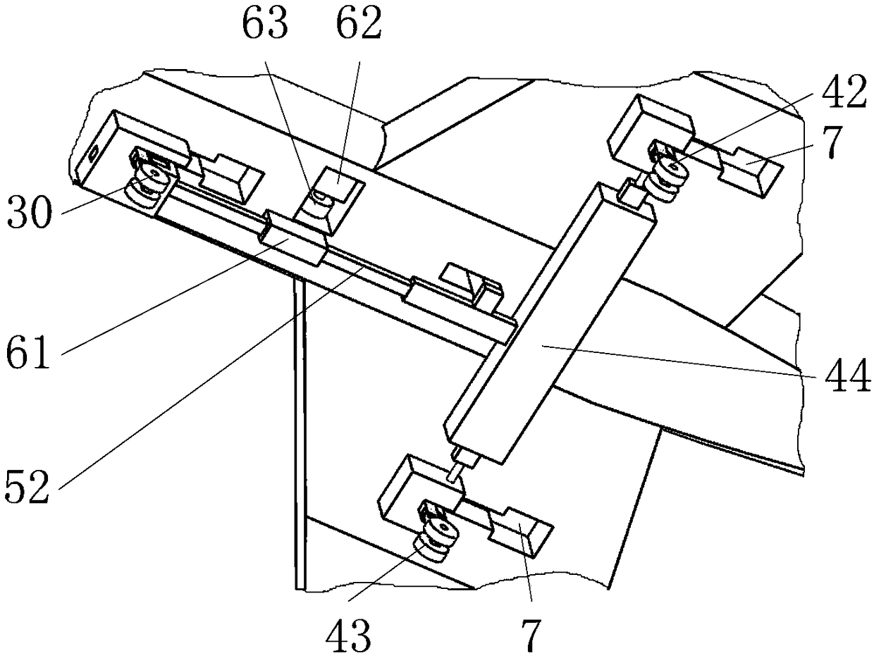
[0055] Such as figure 1 , 2 , 3, it includes a body 1, a first stop block 24, a front wheel mechanism 30, a first rear wheel mechanism 42, a second rear wheel mechanism 43, a limit mechanism 44, a rack mechanism 52, a steering gear 62, Among them such as figure 2 As shown, the body 1 is an existing UAV body 1 with fixed wings; Figure 4 , 12 As shown, the front wheel mechanism 30 is installed on the lower end of the body 1 head in a hinged manner; as Figure 13 As shown, the first rear wheel mechanism 42 and the second rear wheel mechanism 43 are symmetrically installed on the lower ends of the two fixed wings on the body 1 in a hinged manner; Figure 5 , 6 , 7, the front wheel mechanism 30, the first rear wheel mechanism 42 and the second rear wheel mechanism 43 are fixed with the folding gear 33 on the corresponding first wheel shaft 35 at the hinge joint of the body 1; Figure 17 As shown, the steering gear 62 drives the folding gears 33 on the three first wheel shaf...


PUM


Abstract

The invention belongs to the field of unmanned aerial vehicles, and particularly relates to an unmanned aerial vehicle with a foldable landing gear. The unmanned aerial vehicle with the foldable landing gear comprises an engine body, a front wheel mechanism, a first rear wheel mechanism and a rack mechanism, and the engine body is an existing unmanned aerial vehicle body with a fixed wing; meanwhile, when the unmanned aerial vehicle lands, the front wheel mechanism, the first rear wheel mechanism and a second rear wheel mechanism have a certain buffering function; the steering engine is proneto being damaged under attack due to high rotating speed of a part of gear parts in the steering engine in the working process; and therefore, the buffering function of the front wheel mechanism, thefirst rear wheel mechanism and the second rear wheel mechanism can avoid the occurrence of a phenomenon of broken teeth of high-speed gears in the steering engine caused by the attack of the ground and sliding wheels when the unmanned aerial vehicle lands, so that a driving device on the unmanned aerial vehicle is ensured not to be damaged, and the service life of the unmanned aerial vehicle is furthest prolonged.

Description

technical field [0001] The invention belongs to the field of unmanned aerial vehicles, in particular to an unmanned aerial vehicle with foldable landing gear. Background technique [0002] At present, there are two types of traditional drones, one is unmanned drones with landing gear, and the other is unmanned drones without landing gear; the landing gear on drones with landing gear rarely has a stacking function. UAVs that do not have a stackable landing gear have a large wind resistance during flight, which affects the range; even if some UAVs have a stackable landing gear, it will increase infinitely due to the complexity of the control method of the landing gear. Man-machine research and development and production costs; traditional UAVs with landing gear generally have two control methods for the landing gear: one is to control the hydraulic pump installed on the body through the motor, and then control the three landing gears through hydraulic pressure. The other is t...

Claims


Application Information

Patent Timeline
Patent Type & Authority Applications(China)
IPC IPC(8): B64C25/36B64C25/12B64C25/24B64C25/62
CPCB64C25/12B64C25/24B64C25/36B64C25/62B64C2025/125
Inventor 不公告发明人
Owner 深圳市富裕泰贸易有限公司
Learn More