Casement window structure and sectional material with window frame and sash integrally connected in penetrating and inserted modes
A technology for casement windows and window frames, which is applied to the arrangement of wing leaves, wing leaf parts, door/window accessories, etc., which can solve problems such as accelerated aging, aggravated loosening of fixing screws, aging speed, and potential safety hazards, and achieves reduction Effect of corrosion aging, elimination of drop risk and occurrence of hidden dangers, complete safety performance
- Summary
- Abstract
- Description
- Claims
- Application Information
AI Technical Summary
Problems solved by technology
Method used
Image
Examples
Embodiment 1
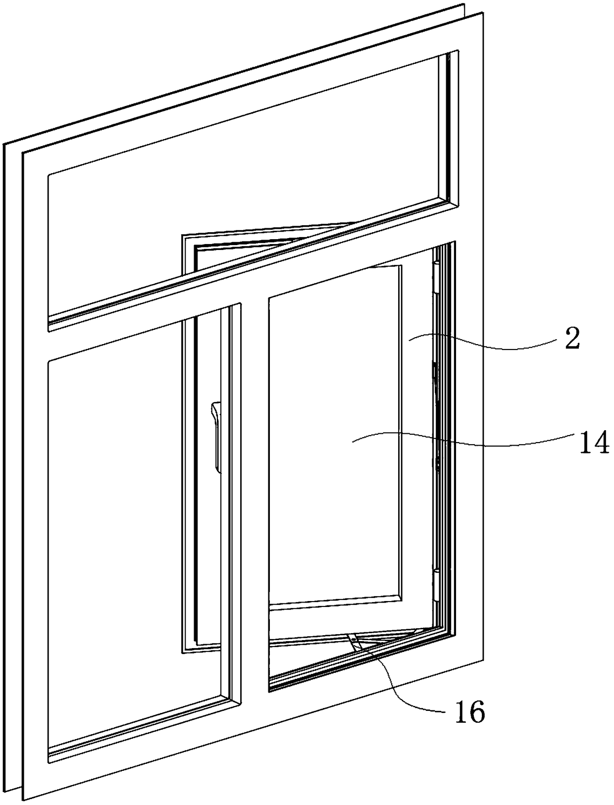
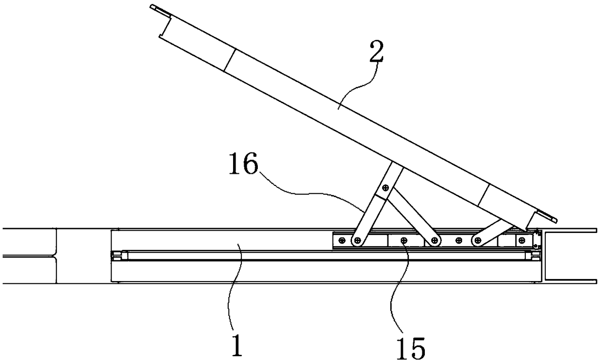
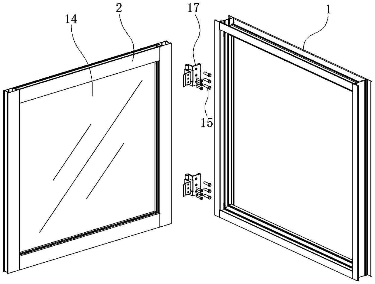
[0029] Embodiment 1: as figure 1 , figure 2 In the connection structure shown in the prior art, the former is a hinged connecting part 16, and the latter is a hinged movable connecting part 17, both of which are characterized by needing to be fixed by 4 to 6 tiny screws 15, That is to say, all the load-bearing forces of the sash 2 and the glass 14 act on these screws 15, which poses a potential safety hazard. The technical solution of Embodiment 1 abandons the traditional screw 15 connection structure and replaces it with a long shaft, thereby realizing a firm connection and fixing function without using screws 15 . Specifically, the technical solution provided by the applicant is as follows: Please refer to the attached image 3 ~ attached Figure 8 , a casement window structure in which a window frame 1 and a window sash 2 are interspersed and connected as a whole, including a window frame 1 and a window sash 2, and the inside of the sash 2 near the axial rotation side o...
Embodiment 2
[0032] Embodiment 2: In this embodiment, the difference from Embodiment 1 lies in its structure: the rotating shaft 6 is composed of a two-stage upper shaft 10 and a lower shaft 11, and the upper shaft 10 The upper part is fixedly installed in the axial hole 5 of the top frame of the window frame 1, and the lower part of the upper shaft rod 10 is inserted into the shaft mounting groove 4 at the upper end of the fan edge profile 3; the lower part of the lower shaft rod 11 is fixedly installed In the axial hole 5 of the bottom frame of the window frame 1, the upper part of the lower shaft rod 11 is inserted into the shaft mounting groove 4 at the lower end of the fan edge profile 3; the shaft mounting groove 4 is opened in sections, including opening The upper shaft groove 12 at the inner upper end of the fan edge profile 3 and the lower shaft groove 13 opened at the inner lower end of the fan edge profile 3 , the upper shaft groove 12 and the lower shaft groove 13 are not commun...
Embodiment 3
[0033] Embodiment 3: The difference from Embodiment 1 is that the rotating shaft 6 runs through the shaft slot 4 end to end and the upper and lower ends of the rotating shaft 6 are installed in the shaft hole 5 in a rotatable manner , the upper end and the lower end of the rotating shaft 6 can rotate in the two shaft holes 5, and the cross section of the rotating shaft 6 can be circular, oval, triangular, quadrangular or polygonal. That is, the opening and closing rotation of the window sash 2 is not dependent on the rotation shaft 6, but depends on the rotation of the upper and lower ends of the rotation shaft 6 in the shaft hole 5, which drives the window sash 2 to rotate together. Therefore, the rotation shaft 6 In addition to the circular axle rod, the section of the cross section can also be a rod of other shapes, which only plays the role of gravity and connection and fixation of the supporting window sash 2, and the two can be regarded as a whole, and this way can also r...
PUM
 Abstract
Description
Claims
Application Information
 - R&D
- Intellectual Property
- Life Sciences
- Materials
- Tech Scout
- Unparalleled Data Quality
- Higher Quality Content
- 60% Fewer Hallucinations
Browse by: Latest US Patents, China's latest patents, Technical Efficacy Thesaurus, Application Domain, Technology Topic, Popular Technical Reports.
© 2025 PatSnap. All rights reserved.Legal|Privacy policy|Modern Slavery Act Transparency Statement|Sitemap|About US| Contact US: help@patsnap.com


