
Soil shear strength detection system based on shear wave velocity measurement

A shear strength and detection system technology, applied in the direction of applying stable shear force to test material strength, measuring device, strength characteristics, etc., can solve the problem of high signal synchronization requirements, large errors, and difficulty in accurately determining shear waves Arrival time and other issues to achieve the effect of reducing the near-field effect and increasing reliability

Inactive Publication Date: 2019-02-01
杭州载博电子科技有限公司
View PDF0 Cites 0 Cited by
  • Summary
  • Abstract
  • Description
  • Claims
  • Application Information

AI Technical Summary

Problems solved by technology

In the initial arrival wave method, the first deflection point of the received signal is the arrival position of the shear wave, while the transmitting bending element excites the shear wave and generates a compression wave at the same time. Since the compression wave propagates faster in the soil, the reception The front part of the signal will be distorted due to the influence of the compression wave, resulting in the so-called near-field effect, and it is difficult to accurately determine the arrival time of the shear wave
The cross-correlation method requires more complex data analysis and processing methods to analyze the correlation between the two waveforms, and is not suitable for modular, bus-type on-site high-speed processing circuit design.
Under the combined effect of the above factors, affected by the individual differences of different testing instruments and researchers, the current shear wave velocity is relatively subjective.
The traditional single-shot and single-receive shear wave velocity piezoelectric bending element sensor requires the measurement circuit to have high requirements for signal synchronization, and the test error is relatively large

Method used


Image

  • Soil shear strength detection system based on shear wave velocity measurement
  • Soil shear strength detection system based on shear wave velocity measurement
  • Soil shear strength detection system based on shear wave velocity measurement

Examples


Embodiment Construction

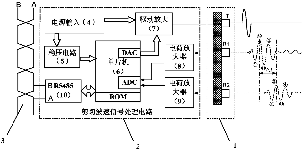
[0021] A soil shear strength detection system based on shear wave velocity measurement, which includes a piezoelectric bending element shear wave velocity sensor (1), a soil shear strength detection signal processing circuit (2) and a serial communication bus (3) .

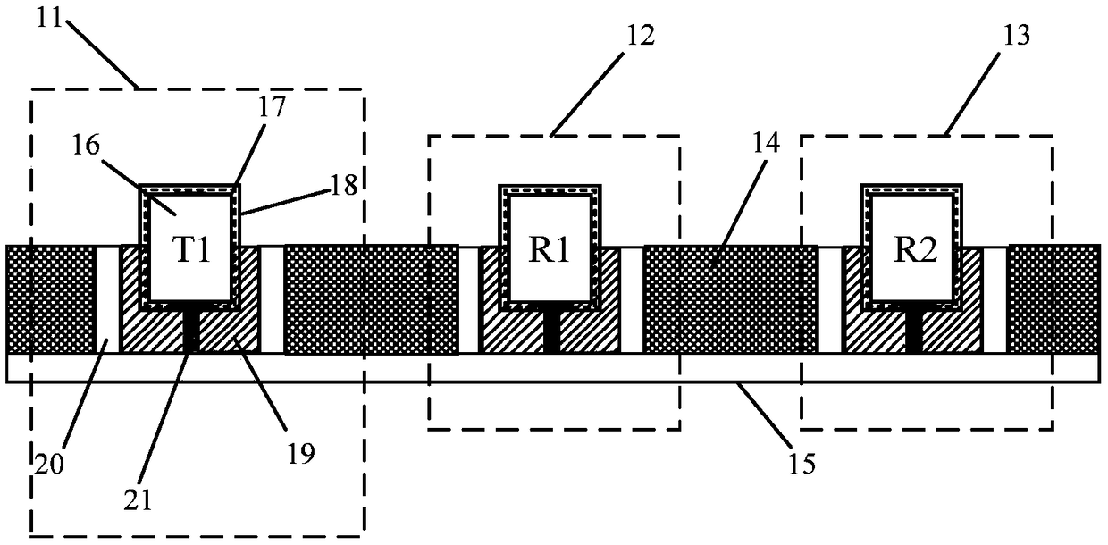
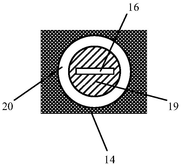
[0022] Such as figure 1 As shown, the soil shear strength detection signal processing circuit includes a power supply (4), a voltage stabilization circuit (5), a single-chip microcomputer (6), a driver amplifier (7), a charge amplifier (8), a charge amplifier (9), and an RS485 driver (10), the piezoelectric bending element shear wave velocity sensor (1) includes the transmitting piezoelectric bending element T (11), the receiving piezoelectric bending element R1 (12), the receiving piezoelectric bending element R2 (13), and the overall support (14 ), wire duct (15).

[0023] Working principle: The power supply (4) supplies power to the overall processing circuit through the voltage regulator circuit (5), and the...


PUM


Abstract

The invention discloses a soil shear strength detection system based on shear wave velocity measurement. The system comprises a piezoelectric bending element shear wave velocity sensor (1), a soil shear strength detection signal processing circuit (2) and a serial communication bus (3); the soil shear strength detection signal processing circuit comprises a power supply (4), a voltage stabilizingcircuit (5), a single-chip microcomputer (6), a drive amplifier (7), a charge amplifier (8), a charge amplifier (9) and an RS485 driver (10); the single-chip microcomputer (6) controls the drive amplifier (7) to output a sine wave to excite a transmitting piezoelectric bending element T (11) to vibrate; a receiving piezoelectric bending element R1 (12) and a receiving piezoelectric bending elementR2 (13) receive a shear wave, and then the shear wave is processed by the charge amplifier (8) and the charge amplifier (9); and the soil shear strength is obtained after a signal is sampled by the single-chip microcomputer (6) and the shear wave velocity is analyzed and calculated by feature point software, and a result is output through the serial communication bus (3).

Description

technical field [0001] The invention belongs to the field of soil shear strength detection, in particular to a soil shear strength detection system based on shear wave velocity measurement. Background technique [0002] Soil shear strength is widely used in engineering mechanics analysis related to building construction and landslide hazards. In various civil engineering construction sites, strict calculation and analysis of soil stability is required before construction, and the shear strength of soil is an important parameter for stability analysis. If the shear strength of soil can be measured accurately, it can often provide great help to the engineering. On the other hand, due to the complex geological environment of our country and the concentrated rainfall, landslide disasters occur frequently. The main cause of landslides is that the soil body forms a failure surface after shear failure. With the gradual expansion of the failure surface, the soil begins to slide an...

Claims


Application Information

Patent Timeline
Patent Type & Authority Applications(China)
IPC IPC(8): G01N3/24
CPCG01N3/24G01N2203/0025G01N2203/0051G01N2203/0676
Inventor 施阁
Owner 杭州载博电子科技有限公司
Learn More