Holographic real-time measuring method and device for measuring particle size of moving particle

A particle size, real-time measurement technology, applied in the direction of measuring devices, particle and sedimentation analysis, particle size analysis, etc., can solve the problem that the holographic measurement method of particle size cannot measure real-time in real time, so as to improve the reconstruction efficiency and increase the measurement error, cheap effect

Pending Publication Date: 2019-02-01
ZHEJIANG UNIV
View PDF7 Cites 6 Cited by
  • Summary
  • Abstract
  • Description
  • Claims
  • Application Information

AI Technical Summary

Problems solved by technology

[0007] The purpose of the present invention is to provide a holographic real-time measurement method and device for measuring the particle size of moving particles, which solves the problem that the current holographic measurement me...

Method used


Image

  • Holographic real-time measuring method and device for measuring particle size of moving particle
  • Holographic real-time measuring method and device for measuring particle size of moving particle
  • Holographic real-time measuring method and device for measuring particle size of moving particle

Examples


Embodiment 1

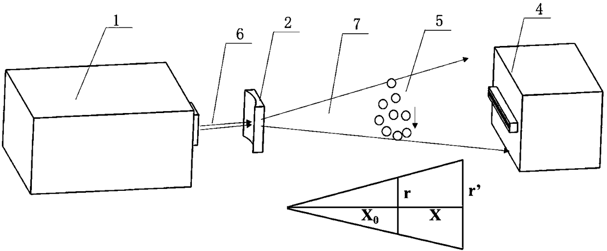
[0043] Such as figure 1 In the holographic real-time measurement device shown, the laser light source 1, the plano-concave cylindrical lens A 2, the plano-convex cylindrical lens B3, and the line array camera 4 are located on the same axis in the order of arrangement, which is a coaxial holographic form. The focal point of the plano-concave cylindrical lens A 2 coincides with the plano-convex cylindrical lens B 3 .

[0044]Specifically, in this embodiment, the laser light source 1 is a semiconductor continuous laser with a wavelength of 532 nanometers. The focal length of the plano-concave cylindrical lens A 2 is 30 mm, the length is 20 mm, and the width is 10 mm; the focal length of the plano-convex cylindrical lens B 3 is 60 mm, the length is 40 mm, and the width is 25 mm. The pixel size of the line scan camera 4 is 10 microns, the number of pixels is 4096×1, the effective measurement area of ​​the line scan camera 4 can reach 4 cm, and the sampling frequency can reach 52 k...

Embodiment 2

[0065] Such as figure 2 In the holographic real-time measuring device shown, the laser light source 1, the plano-concave cylindrical lens A2, and the line array camera 4 are arranged on the same axis according to the sequence, which is a coaxial holographic form.

[0066] The method for measuring the particle size using the holographic real-time measuring device of this embodiment is as in Embodiment 1.


PUM

PropertyMeasurementUnit
Particle sizeaaaaaaaaaa

Abstract

The invention discloses a holographic real-time measuring method for measuring the particle size of a moving particle. The method comprises the steps of: a disk laser beam expanding system generatingdisk laser to irradiate to the moving particle; the disk laser passing through the scattered light of the particle to form object light; taking the sheet laser which did not pass through the particleas reference light; the object light interfering with the reference light to form a one-dimensional holographic stripe, and recording the one-dimensional holographic stripe; reconstructing a hologramformed by the recorded one-dimensional holographic stripe to obtain a particle image; and calculating the particle size according to the number and the size of the pixels in the particle image. The invention further discloses a holographic real-time measuring device for measuring the particle size of the moving particle. The holographic real-time measuring device comprises disk laser beam expanding system, a linear array camera, and a holographic data processing unit, wherein the disk laser beam expanding system comprises a laser light source and a cylindrical lens. According to the holographic real-time measuring method and the device for measuring the particle size of the moving particle, real-time and rapid monitoring of the particle size of the particle can be realized by reducing collection and reconstruction data dimensions and reducing data volume.

Description

technical field [0001] The invention relates to the field of on-line particle size measurement, in particular to a holographic real-time measurement method and device for measuring the particle size of moving particles. Background technique [0002] In thermal power generation, metallurgy, cement and other industries, the measurement of particle size and particle size distribution is an indispensable link, which is of great significance for efficient and safe production. [0003] Particle size measurement methods can be divided into two categories: offline methods and online methods. Off-line methods mainly include sieving method, sedimentation method and microscopy method, and the most widely used method in industry is the sieving method. Online methods mainly include electrical methods, acoustic methods and optical methods, with laser particle size analyzer as the main representative. [0004] The basic principle of the sieving method is to use a series of sieves with di...

Claims


Application Information

Patent Timeline
IPC IPC(8): G01N15/02
CPCG01N15/0205G01N15/0211G01N15/0227G01N2015/0233
Inventor 吴迎春吴学成高翔陈玲红邱坤赞骆仲泱岑可法管文洁金其文
Owner ZHEJIANG UNIV
Why Eureka
Try Eureka