Connection structure of wiring terminal and enameled wire, method, coil assembly and motor

A technology of terminal and connection structure, which is applied in the parts, connections, circuit/collector parts of connecting devices, etc., can solve the problems such as easy breaking or bumping of enameled wires, defective products, and easy loosening and falling off of enameled wires. , to achieve the effect of removing the length controllable, prolonging the life, and eliminating the hidden danger of pulling and breaking.

Pending Publication Date: 2019-02-01
HANYU GRP CO LTD
View PDF3 Cites 6 Cited by
  • Summary
  • Abstract
  • Description
  • Claims
  • Application Information

AI Technical Summary

Problems solved by technology

However, on the one hand, this terminal makes the fixing (winding) of the enameled wire more labor-intensive, and the fixed enameled wire is still easy to loosen and fall off; It is easy to be broken or bruised, resulting in defective products and motor failure

Method used


Image

  • Connection structure of wiring terminal and enameled wire, method, coil assembly and motor
  • Connection structure of wiring terminal and enameled wire, method, coil assembly and motor
  • Connection structure of wiring terminal and enameled wire, method, coil assembly and motor

Examples


Embodiment 1

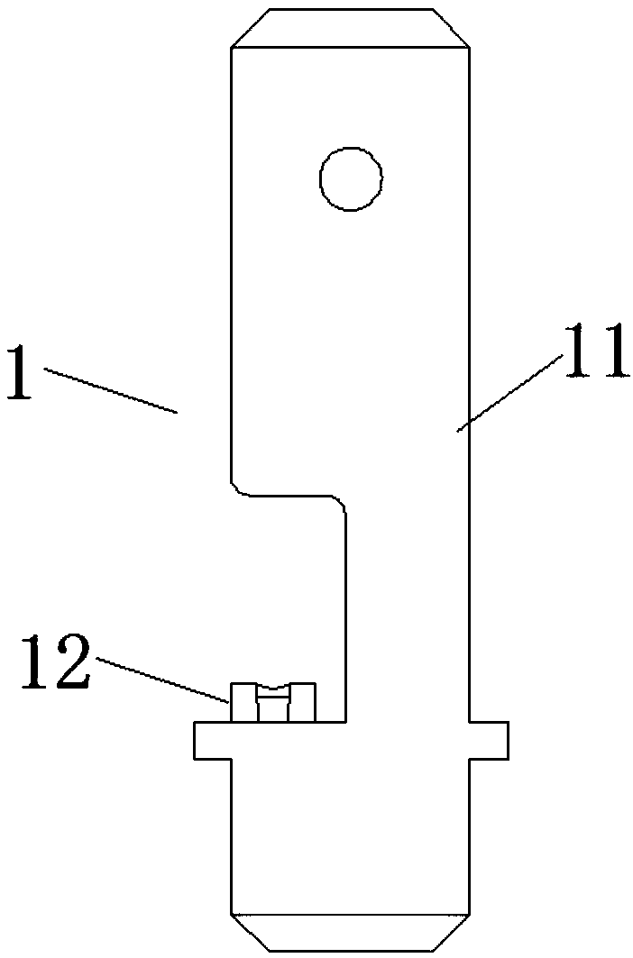
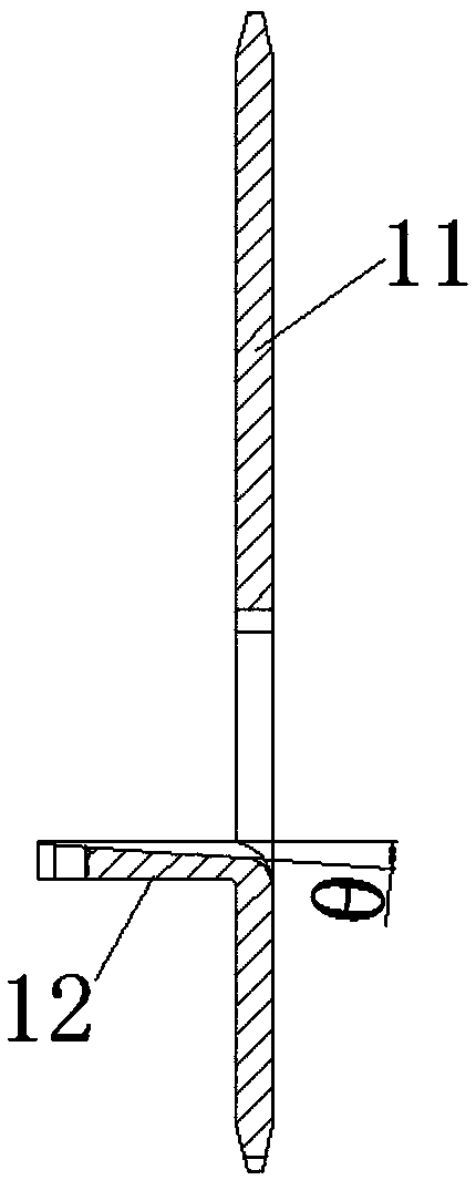
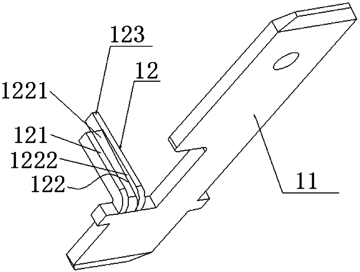
[0065] see Figure 1~3 , which is a schematic structural view of the terminal of the present invention.

[0066] The terminal 1 of this embodiment includes a terminal body 11 and a terminal post 12 . The terminal post 12 is used to connect with the terminal of the enameled wire. The terminal post 12 is fixed on the terminal body 11 and includes a first surface 121 , a first groove 122 and a wire end winding post 123 . The first groove 122 is formed downwardly from the first surface 121 , and includes two side surfaces 1222 and a bottom surface 1221 . In this embodiment, the angle θ between the bottom surface 1221 of the first groove and the first surface 121 is 15°. In other embodiments, the angle θ is preferably in the range of 0-20°, that is, the first groove The bottom surface 1221 of the first surface 121 can be parallel to the first surface 121 or inclined. In this embodiment, the enameled wire is aluminum enameled wire, and in other embodiments, traditional copper ena...

Embodiment 2

[0068] see Figure 4~5 , the terminal 1 of this embodiment includes a terminal body 11, a terminal 12 and a fixed terminal 13, the terminal 12 does not include a wire end winding column 123, other components and shapes of the terminal 12, the terminal body 11 and the terminal 12 The structural relationship is the same as in Embodiment 1, and the included angle θ is 20° in this embodiment.

[0069] In this embodiment, the section of the fixed terminal 13 is U-shaped, and its inner surface is provided with a plurality of tooth-shaped structures 131 to further prevent the loosening of the enameled wire. In other embodiments, the tooth-shaped structures 131 may not be provided. Structure 131. In the initial state, the fixed terminal 13 and the terminal 12 are separated and independent from each other, and the fixed terminal 13 can be stamped to be fixed with the terminal 12 through a stamping process, and wrapped on the three outer surfaces of the terminal, including the first su...

Embodiment 3

[0072] see Figure 8-9, The terminal 1 of this embodiment includes a terminal body 11 , a terminal post 12 and a fixed terminal 13 . The shape and structure of the terminal 12 in this embodiment, and the structural relationship between the terminal body 11 and the terminal 12 are the same as in Embodiment 1, and the included angle θ in this embodiment is 10°.

[0073] In this embodiment, the fixed terminal 13 is fixed on the terminal 12, and includes a crimping portion 132 and a fixing portion 133 connected to each other. The fixed terminal 13 is fixed on the side wall of the terminal 12 through the fixing portion 133. The crimping portion 132 can pass The crimping covers the first surface 121 of the terminal 12 . The initial state of the fixed terminal 13, such as Figure 8 As shown, the fixed part 133 is fixed to the terminal 12, and the crimping part 132 is located above the terminal 12 and does not contact the terminal 12; after the crimping part 132 is stamped, it looks...


PUM


Abstract

The invention provides a connection structure of a wiring terminal and an enameled wire, a connection method, a coil assembly and a motor. The wiring terminal of the present invention comprises a wiring terminal body, and a wiring post which is connected with the wiring end of the enamel wire; the wiring post is fixed to the wiring terminal body and includes a first surface, and a first groove which is formed in the first surface and faces downwardly; the connection structure of the wiring terminal and the enameled wire includes the enameled wire and the wiring terminal; the wiring end of theenameled wire is arranged in the first groove; a fixing terminal is crimped and is fixed to the wiring end of the enameled wire and the wiring post; and the wiring end of the enameled wire is butt-welded to the fixing terminal and the wiring post. With the connection structure, and the connection method of the invention adopted, the enameled wire can be arranged and fixed on the wiring post more conveniently and firmly, the enameled wire can be favorably protected, and the enameled wire is unlikely to be damaged due to external forces; the butt-welded connection of the enameled wire and the wiring post is realized, and therefore, the length of the removed sheath of the enameled wire can be controlled, and the service life of the coil assembly or motor can be prolonged.

Description

technical field [0001] The invention belongs to the field of wiring and its connection, and in particular relates to a wiring terminal, its connection structure and connection method with an enameled wire, a coil assembly and a motor. Background technique [0002] The enameled wires used in motors can be copper wires or aluminum wires. In the 1970s, studies have been made on the application of aluminum wires to motors. Whether it is a copper enameled wire or an aluminum enameled wire, the connection between the existing enameled wire and the terminal mainly adopts tin soldering. The soldering method needs to use liquid tin to remove the enameled wire paint. The specific method is to first immerse the enameled wire head in a high-temperature tin furnace to melt off the enameled wire on the surface. In order to fix the enameled wire, the terminal post is cylindrical. The way to fix it on the terminal. However, on the one hand, this terminal makes the fixing (winding) of the ...

Claims


Application Information

Patent Timeline
Patent Type & Authority Applications(China)
IPC IPC(8): H01R13/405H01R43/02
CPCH01R13/405H01R43/02H01R43/0263
Inventor 王红标敖林李昌建
Owner HANYU GRP CO LTD
Why Eureka
Try Eureka