Power control cabinet

A technology for power control cabinets and cabinets, which is applied in electrical components, substation/distribution device enclosures, substation/switch layout details, etc. issues of sex

Active Publication Date: 2019-02-01
安徽龙和电力集团有限公司
View PDF5 Cites 4 Cited by
  • Summary
  • Abstract
  • Description
  • Claims
  • Application Information

AI Technical Summary

Problems solved by technology

[0002] In the secondary equipment of the power system, a large number of electronic equipment requires long-term unstoppable operation. With the operation of the equipment, a large amount of dust accumulates on the appearance of the equipment. After a long time, a layer of dust covers the surface of the equipment, which affects the heat dissipation of the electronic equipment and seriously affects the service life of the equipment. At the same time, it is easy to cause electrostatic breakdown. However, when cleaning the dust regularly, because the equipment is fixed in the cabinet for a long time, it cannot be removed at will. Over time, the accumulation of dust will affect the heat dissipation, and even the electrostatic breakdown will cause the equipment to stop running. It is easy to cause personal injury or death by electric shock, which not only causes economic losses but also affects the stable operation of the power grid. Although the dust is small, it is extremely harmful. Therefore, dust cleaning of electronic equipment has become a difficult problem in the daily maintenance of the computer room, and because the height of the power control cabinet is relatively high. High, in the cleaning mode, the interior cannot be effectively cleaned, and the safety of personnel and equipment cannot be guaranteed when building a ladder. Therefore, people have proposed a cleaning device that can automatically clean and clean the dust in the power control cabinet. collect

Method used


Image

  • Power control cabinet
  • Power control cabinet
  • Power control cabinet

Examples


Embodiment Construction

[0019] The technical solutions in the embodiments of the present invention will be clearly and completely described below in conjunction with the accompanying drawings in the embodiments of the present invention. Obviously, the described embodiments are only a part of the embodiments of the present invention, rather than all the embodiments. Based on the embodiments of the present invention, all other embodiments obtained by those of ordinary skill in the art without creative work shall fall within the protection scope of the present invention.

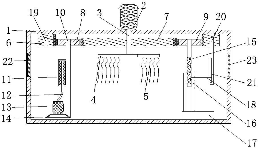
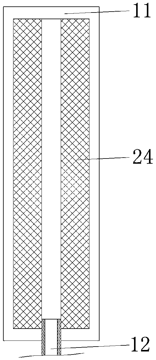
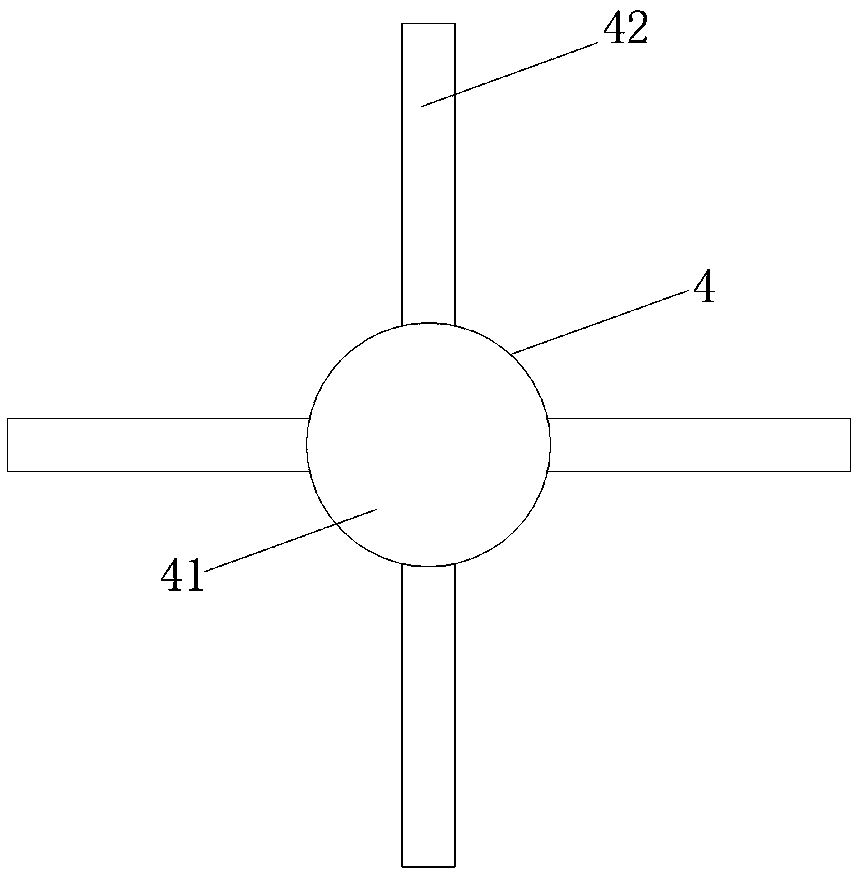
[0020] See Figure 1 to Figure 3 , The present invention provides a technical solution: a power control cabinet, including a cabinet body 1, the cabinet body 1 is the power control cabinet, the inner bottom is designed with a space for loading power control equipment, we are based on the cleanness of the space According to the invention, the sides of the cabinet 1 close to the top are provided with through grooves 22, and the inner wall ...


PUM


Abstract

The invention discloses a power control cabinet which comprises a cabinet body. A motor is fixedly connected with the upper surface of the cabinet body; a rotating shaft I is fixedly connected to thebottom of an output shaft at the motor; the bottom of the rotating shaft I penetrates the upper surface of the cabinet body and is fixedly connected with a connecting member; and a ribbon is fixedly connected to the lower surface of the connecting member. An out gear ring is fixedly connected to the top of the inner wall of the cabinet body. A sun gear is fixedly connected to the side, close to the top, of the rotating shaft I; a planetary gear I and a planetary gear II are engaged with the gap between the sun gear and the outer gear ring respectively and symmetrically; rotating shafts II arefixedly connected to the inner walls of the planetary gear I and the planetary gear II; and a collection bag is fixedly connected to the side of the rotating shaft II of the planetary gear I. According to the invention, on the basis of the cooperative usage of the structures, problems the control cabinet is not convenient to clean and can not be cleaned completely are solved; and the work efficiency is improved.

Description

Technical field [0001] The invention relates to the technical field of cleaning devices, in particular to a power control cabinet. Background technique [0002] In the secondary equipment of the power system, a large number of electronic equipment requires long-term non-stop operation. As the equipment operates, a large amount of dust accumulates on the appearance of the equipment. Over time, a layer of dust is covered on the surface of the equipment, which affects the heat dissipation of electronic equipment and seriously affects the service life of the equipment At the same time, it is easy to cause electrostatic breakdown. However, when the dust is cleaned regularly, because the equipment is fixed in the cabinet for a long time, it cannot be removed at will. The accumulation of dust will affect the heat dissipation and even the electrostatic breakdown will cause the equipment to stop running. It is easy to get an electric shock and cause personal injury and death, which not on...

Claims


Application Information

Patent Timeline
Patent Type & Authority Applications(China)
IPC IPC(8): H02B1/30H02B1/28H02B1/56H02B1/54
CPCH02B1/28H02B1/30H02B1/54H02B1/565
Inventor 史少锋
Owner 安徽龙和电力集团有限公司
Why Eureka
Try Eureka