A continuous processing equipment that uses electromagnetic suction to realize automatic cutting and waste collection

A technology of automatic blanking and electromagnetic suction, which is applied in metal processing equipment, metal processing, metal processing machinery parts, etc., can solve the problem that waste chips cannot be processed, reclaimed materials and workpieces, waste chips cannot be recycled, and unstable Recycling effect and other issues, to achieve the effect of preventing accumulation, high work efficiency, and reasonable structural design

Active Publication Date: 2019-01-25
XUZHOU TIANTAI MACHINERY MFG
View PDF7 Cites 0 Cited by
  • Summary
  • Abstract
  • Description
  • Claims
  • Application Information

AI Technical Summary

Problems solved by technology

[0007] The purpose of the present invention is to address the deficiencies of the prior art, to provide a continuous processing equipment that uses electromagnetic suction to realize automatic cutting and waste collection, and overcomes the waste waste that cannot be recycled or the recovery is unstable during machine tool processing. Not good, the waste after recycling cannot be processed and it is more troublesome to take materials and workpieces after waste recycling

Method used


Image

  • A continuous processing equipment that uses electromagnetic suction to realize automatic cutting and waste collection
  • A continuous processing equipment that uses electromagnetic suction to realize automatic cutting and waste collection
  • A continuous processing equipment that uses electromagnetic suction to realize automatic cutting and waste collection

Examples


Embodiment 1

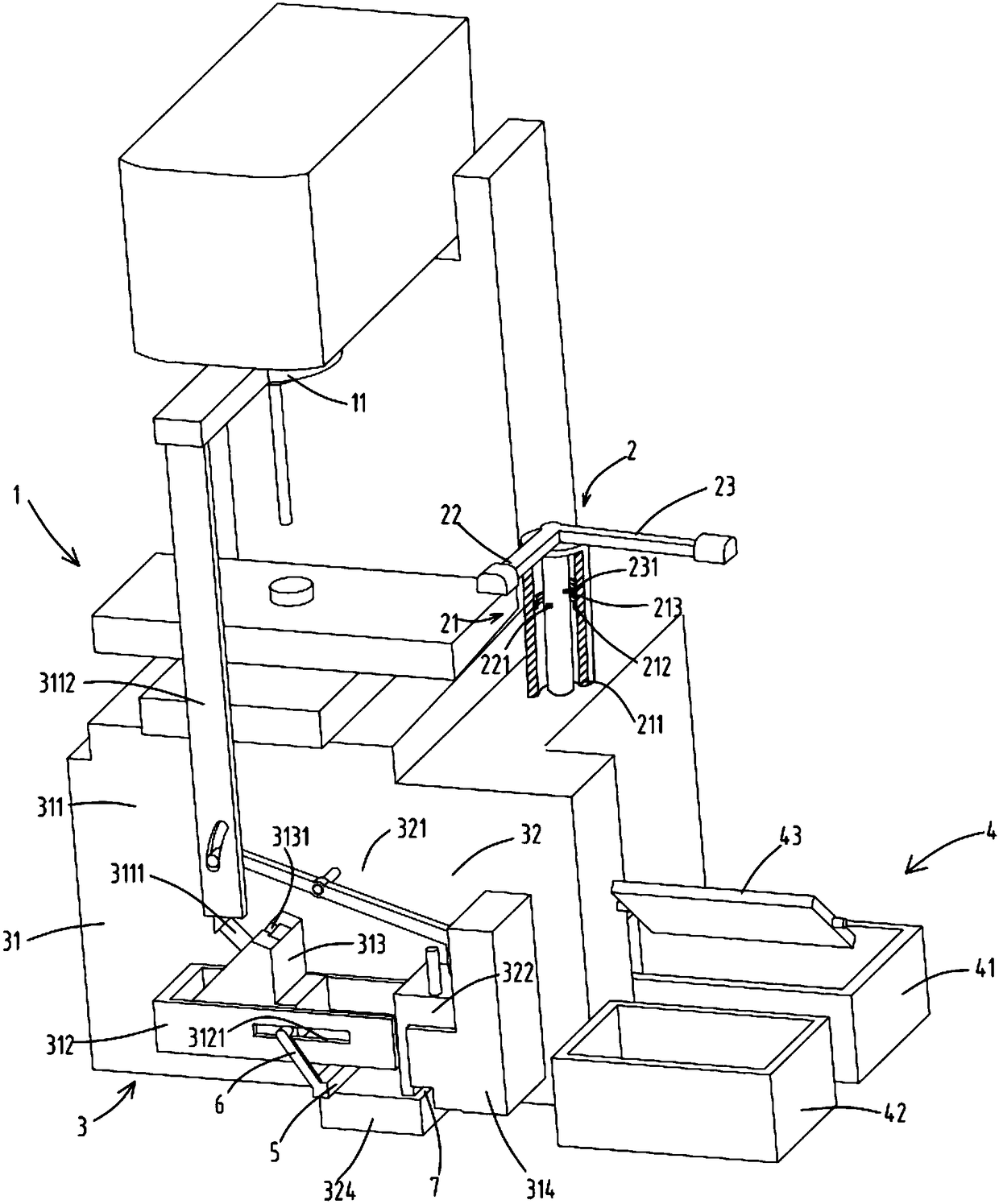
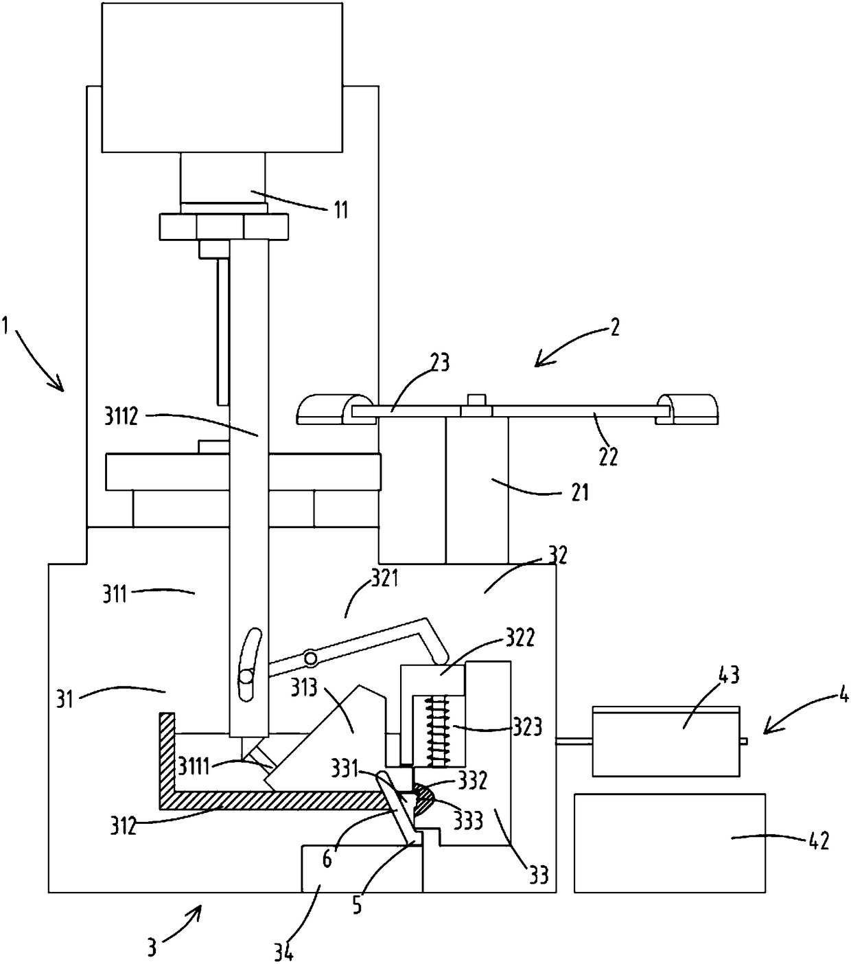
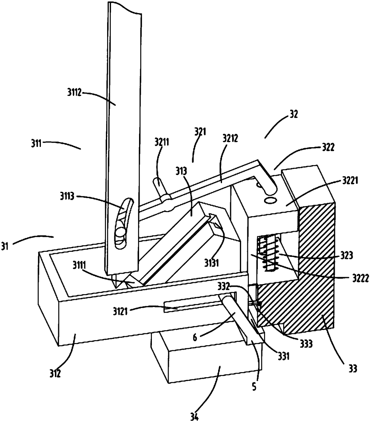
[0035] figure 1 It is a schematic diagram of a continuous processing equipment that uses electromagnetic suction to realize automatic feeding and waste collection. figure 2 It is a schematic front view of a continuous processing equipment that uses electromagnetic suction to realize automatic feeding and waste collection. image 3 It is a partial structural schematic diagram of a continuous processing equipment that uses electromagnetic suction to realize automatic cutting and waste collection. Figure 4 It is a schematic diagram of the structure of the inclined block and the transmission rod, Figure 5 A cross-sectional schematic diagram of the position of the control part, Figure 6 It is a cross-sectional schematic diagram of the position of the control part. Such as figure 1 , figure 2 , image 3 , Figure 4 , Figure 5 and Figure 6 As shown, what is provided in this embodiment is a continuous processing equipment that uses electromagnetic suction to realize au...

Embodiment 2

[0047] Such as figure 1 , figure 2 , image 3 , Figure 4 , Figure 5 , Figure 6 As shown, the components that are the same as or corresponding to those in the first embodiment are marked with the corresponding reference numerals in the first embodiment. For the sake of simplicity, only the differences from the first embodiment will be described below. The difference between the second embodiment and the first embodiment is that: the machine tool 1, the waste collection device 3 and the material collection part 4 form an included angle of 120 degrees with the power shaft 24 as the center;

[0048] The setting of this kind of angle can ensure that the two steps of material suction by the material adsorption mechanism 22 and waste removal by the waste adsorption mechanism 23 are carried out at the same time, and the two steps of waste suction by the waste adsorption mechanism 23 and dropping by the material adsorption mechanism 22 Simultaneously, so that the number of tim...

Embodiment 3

[0050] Such as figure 1 , figure 2 , image 3 , Figure 4 , Figure 5 , Figure 6 As shown, the parts that are the same as or corresponding to those in the second embodiment are marked with the corresponding reference numerals in the second embodiment. For the sake of simplicity, only the differences from the second embodiment will be described below. The difference between the third embodiment and the second embodiment is that the material collecting part 4 includes a material box a41, a material box b42, and a receiving plate 43 arranged above the material box a41 and the material box b42; the receiving plate 43 are rotatably arranged on the lathe 1; can control material to fall in which feed box by rotating receiving plate 43, can rotate receiving plate 43 and make material fall in the standby feeding box when one of the feed boxes is full and it is too late to transfer.

[0051] Working process: After the machine tool 1 processes a material, the control mechanism 21 ...


PUM


Abstract

The invention relates to continuous machining equipment achieving automatic discharging and waste scrap collecting through electromagnetic attraction. The continuous machining equipment comprises a machine tool, a waste scrap collecting device and a material picking device, wherein the waste scrap collecting device comprises a transverse squeezing mechanism and a longitudinal squeezing mechanism; the material picking device comprises a control mechanism, a material attraction mechanism driven by the control mechanism to rotate around a power shaft, and a waste scrap attraction mechanism; and the control mechanism comprises a supporting base, an electric connector a of which one end is electrically connected with the material attraction mechanism and fixed to the power shaft, an electric connector b of which one end is electrically connected with the waste scrap attraction mechanism and fixed to the power shaft, an arc-shaped electric connection sheet a which is fixed to the inner wall of the supporting base and is matched with the electric connector a for turning on or off power, and an arc-shaped electric connection sheet b which is fixed to the inner wall of the supporting base and is matched with the electric connector b for turning on or off the power. According to the continuous machining equipment, the problems that in the machining process of the machine tool, waste scraps cannot be recycled, or recycling is unstable, or the recycling effect is not good, the recycled waste scraps cannot be treated, and material picking and workpiece picking are troublesome after the waste scraps are recycled are solved.

Description

technical field [0001] The invention belongs to the technical field of machining equipment, in particular to a continuous processing equipment that utilizes electromagnetic suction to realize automatic feeding and waste collection. Background technique [0002] In the process of processing, processing waste will be generated. In the prior art, an air gun is generally used to blow air on the processed workpiece to blow away the waste and then remove the workpiece. In this way, the waste is blown to every corner and cannot be cleaned. Waste chips are effectively recovered, and it is troublesome to remove the workpiece. [0003] A Chinese utility model patent with the authorized notification number CN204430940U discloses a waste chip recycling device for a drilling machine, which uses an air blowing device to blow the waste chips through the funnel hole into the funnel for recycling, so as to realize the separation of various metal waste chips Recycling reduces the harm of met...

Claims


Application Information

Patent Timeline
Patent Type & Authority Patents(China)
IPC IPC(8): B23Q7/00B23Q11/00
CPCB23Q7/00B23Q11/0042B23Q11/0064
Inventor 周向荣
Owner XUZHOU TIANTAI MACHINERY MFG
Why Eureka
Try Eureka