Ultralow consumption current-reuse low-noise amplifier based on substrate bias

A low-noise amplifier and current multiplexing technology, applied in amplifiers, high-frequency amplifiers, radio frequency amplifiers, etc., can solve the problems of high noise coefficient and low-noise amplifier power consumption, achieve low noise, reduce circuit power consumption, and achieve The effect of current multiplexing

Active Publication Date: 2019-02-01
成都智芯测控科技有限公司
View PDF5 Cites 0 Cited by
  • Summary
  • Abstract
  • Description
  • Claims
  • Application Information

AI Technical Summary

Problems solved by technology

[0004] The technical problem to be solved by the present invention is that the existing low-noise amplifiers have high power consumption and high noise figure, and the purpose is to provide a substrate-bias-based ultra-low current multiplexing low-noise amplifier to solve the above problems

Method used


Image

  • Ultralow consumption current-reuse low-noise amplifier based on substrate bias
  • Ultralow consumption current-reuse low-noise amplifier based on substrate bias
  • Ultralow consumption current-reuse low-noise amplifier based on substrate bias

Examples


Embodiment 1

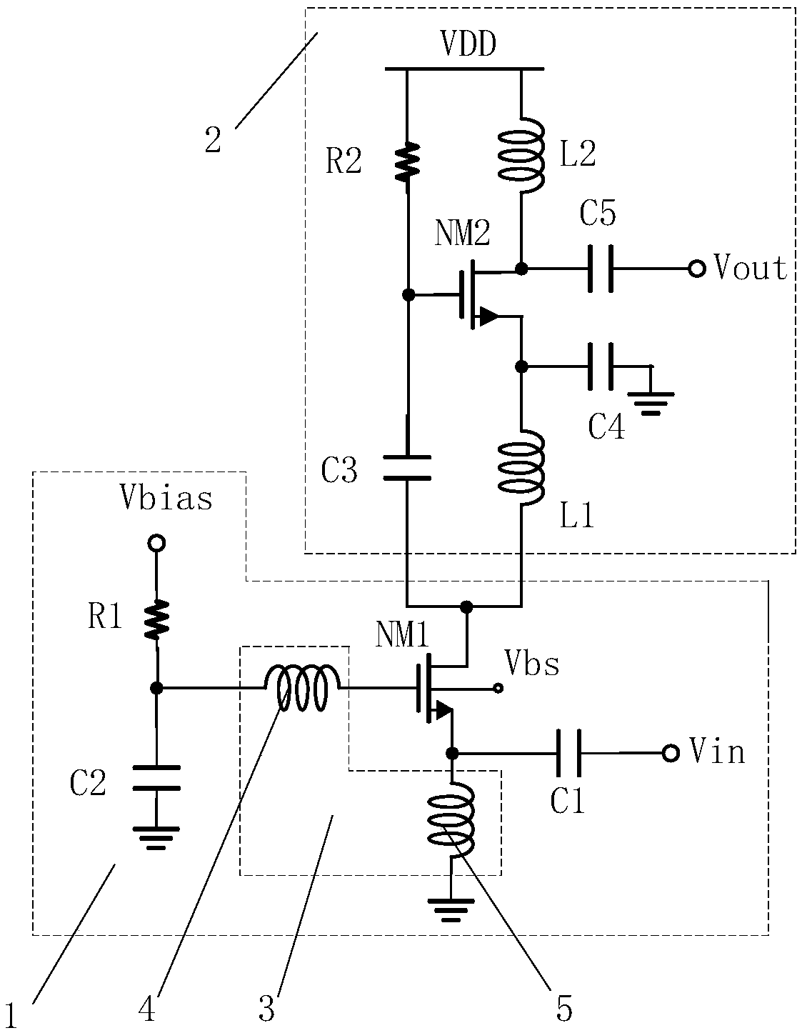
[0034] Such as figure 1 As shown, the present invention is an ultra-low current multiplexing low noise amplifier based on substrate bias, including an input circuit 1 and an output circuit 2 connected in sequence; the input circuit includes a first resistor R1, a first capacitor C1 , the first MOS tube NM1 and the transformer 3; the transformer 3 includes a first coil 4 and a second coil 5 of mutual inductance; one end of the R1 and one end of the first coil 4 have a common node, and the other end of the R1 is biased Voltage Vbias, the other end of the first coil 4 is connected to the gate of NM1; one end of C1, the source of NM1, and one end of the second coil 5 have a common node, and the other end of C1 is connected to the input voltage Vin, the second coil 5 The other end of NM1 is connected to the ground, the drain of NM1 is connected to the output circuit 2; the substrate of NM1 is connected to the substrate bias voltage Vbs.

[0035] When this embodiment is implemented...

Embodiment 2

[0037] Such as figure 1As shown, this embodiment is based on Embodiment 1, and the input circuit 1 further includes a second capacitor C2; one end of the C2 is connected to the common node of R1 and the first coil 4, and the other end of C2 is grounded.

[0038] When this embodiment is implemented, the second capacitor C2 is grounded, thereby forming an AC ground, realizing filtering of the entire device, and reducing noise.

Embodiment 3

[0040] Such as figure 1 As shown, this embodiment is based on Embodiment 1, and the output circuit 2 includes a second resistor R2, a second MOS transistor NM2, a third capacitor C3, a fifth capacitor C5, a first inductor L1, and a second inductor L2 ; One end of R2, one end of C3 and the gate of NM2 have a common node, and the other end of R2 is connected to the operating voltage VDD, and the other end of C3 is connected to the drain of NM1; one end of the L2, one end of C5 and NM2 The drains share a node, and the other end of L2 is connected to the working voltage VDD, and the other end of C5 is connected to the output voltage Vout; one end of the L1 and the source of the NM2 share a node, and the other end of L1 is connected to the drain of the NM1.

[0041] When this embodiment is implemented, VDD passes the bias voltage to NM2 through R2, and because one end of C3 and the gate of NM2 share a node, and C3 is connected to the drain of NM1, this current branch can be used as...


PUM


Abstract

The invention discloses an ultralow consumption current-reuse low-noise amplifier based on substrate bias. The ultralow consumption current-reuse low-noise amplifier comprises an input circuit and anoutput circuit connected in order; the input circuit comprises a first resistor R1, a first capacitor C1, a first MOS tube NM1 and a transformer; the transformer comprises a first coil and a second coil which are mutually induced; one end of the R1 and one end of the first coil share the same node, the other end of the R1 is connected with a bias voltage Vbias, and the other end of the first coilis connected with the grid of the NM1; one end of the C1, the source of the NM1 and one end of the second coil share the same node, the other end of the C1 is connected with an input voltage Vin, theother end of the second coil is grounded, and the drain of the NM1 is connected with the output circuit; and the substrate of the NM1 is connected with the substrate bias voltage Vbs. The invention discloses an ultralow consumption current-reuse low-noise amplifier based on substrate bias; and the low power consumption, the low noise and the high gain of the whole device are realized due to mutualeffect of the transformer and the substrate bias voltage.

Description

technical field [0001] The invention belongs to the field of radio frequency CMOS integrated circuits, and in particular relates to an ultra-low current consumption multiplexing low noise amplifier based on substrate bias. Background technique [0002] In the wireless LAN radio frequency front-end system, the low noise amplifier is a key component, which directly affects the performance of the whole system. Its main function is to amplify the weak signal received from the antenna, and at the same time output the signal to the subsequent mixer. The noise introduced in this process must be very low. As the first-stage low-noise amplifier of the receiving system, Its noise performance directly affects the noise performance of the entire system; secondly, its parameters such as gain, linearity, power consumption, and area directly affect the performance of the entire receiver. These performance parameters affect each other and restrict each other, how to find a compromise becom...

Claims


Application Information

Patent Timeline
Patent Type & Authority Applications(China)
IPC IPC(8): H03F1/26H03F1/02H03F3/19H03G3/30
CPCH03F1/0205H03F1/0211H03F1/26H03F1/483H03F1/486H03F3/19H03G3/3036H03F2200/451
Inventor 牟首先王晓阳马凯学孟凡易
Owner 成都智芯测控科技有限公司
Why Eureka
Try Eureka