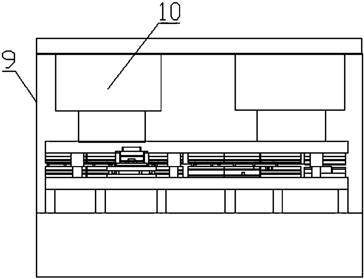
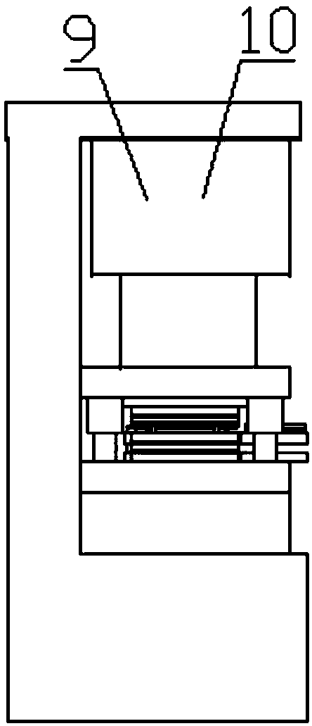
Wiring hidden box machining tool
A technology for processing machine tools and cassettes, applied in manufacturing tools, other manufacturing equipment/tools, etc., can solve the problems of low efficiency of wiring cassettes, and achieve the effect of precise shape, high processing efficiency and precise hole position
- Summary
- Abstract
- Description
- Claims
- Application Information
AI Technical Summary
Problems solved by technology
Method used
Image
Examples
Embodiment 1
[0072] Such as Figure 10 to Figure 13 As shown, a junction box is shaped as a rectangular box with an opening, and consists of a bottom plate and four side plates connected to the bottom plate. Wherein, the base plate is provided with mounting hole 81 and four knock-out holes 86; two opposite side plates are provided with two knock-out holes 86, an ear seat 82 and two connection holes 85, ear seat 82 There are earholes 821 on the top, and there is a cylindrical flange 822 below the earhole 821. There are threads in the earhole 821 and the cylindrical flange 822; the other pair of opposite side plates are provided with two knock-out holes 86 and a card slot. 84 and two buckles 83 located on both sides of the slot 84. Knock out hole 86 is the hole position that wiring cassette is used for wiring, and it is covered with circular plate, and circular plate is only connected with box body by connecting rib 861, and can be knocked selectively to circular plate according to actual s...
Embodiment 2
[0089] The structure of the processing machine tool of this embodiment is basically the same as that of the wiring box processing machine tool of embodiment 1, the difference is that the upper ends of the punching and tapping modules and the punching modules are along the direction of the feeding direction. Positioning columns 5 are installed on both sides, and the upper part of each positioning column 5 is provided with an annular groove 51 located on the same horizontal plane. The sheet material 7 passes through the annular groove 51 and is supported by the annular groove 51. Between column 5. This structure reduces the impact force when the upper and lower modules process the sheet material 7, and increases the service life of the machine tool. If the sheet material 7 is directly placed on the lower mold for processing, a larger impact force is required to form the sheet material 7, which is easy to cause damage to the machine tool.
Embodiment 3
[0091] The processing machine tool of this embodiment is basically the same structure as the wiring box processing machine tool of Embodiment 2, the difference is that the upper mounting plate and the middle mounting plate of each upper group are connected by a spring, and on the one hand, the mounting plate The movement of the upper mold acts as a buffer to reduce the impact force, and on the other hand, it also makes the working movement of the upper mold more smooth.
PUM
 Abstract
Description
Claims
Application Information
 - R&D
- Intellectual Property
- Life Sciences
- Materials
- Tech Scout
- Unparalleled Data Quality
- Higher Quality Content
- 60% Fewer Hallucinations
Browse by: Latest US Patents, China's latest patents, Technical Efficacy Thesaurus, Application Domain, Technology Topic, Popular Technical Reports.
© 2025 PatSnap. All rights reserved.Legal|Privacy policy|Modern Slavery Act Transparency Statement|Sitemap|About US| Contact US: help@patsnap.com


