Backlight source die-cutting discharge automatic cutting device

An automatic cutting device and backlight technology, applied in metal processing and other directions, can solve problems such as complex structures, and achieve the effects of simple operation, labor saving, and simple structure

Inactive Publication Date: 2019-02-05
YANCHENG SANDING ELECTRONICS TECH CO LTD
View PDF14 Cites 2 Cited by
  • Summary
  • Abstract
  • Description
  • Claims
  • Application Information

AI Technical Summary

Problems solved by technology

Patent No. CN 205183901 U proposes a pressing and cutting device for iron sheets. The device is not equipped with a dust absorbing device. The patent uses a hob to cut iron sheets, and the structure is complicated. Therefore, the present invention proposes a backlight Die-cutting and discharging automatic cutting device to solve the above problems

Method used


Image

  • Backlight source die-cutting discharge automatic cutting device
  • Backlight source die-cutting discharge automatic cutting device
  • Backlight source die-cutting discharge automatic cutting device

Examples


Embodiment Construction

[0019] The following will clearly and completely describe the technical solutions in the embodiments of the present invention with reference to the accompanying drawings in the embodiments of the present invention. Obviously, the described embodiments are only some, not all, embodiments of the present invention.

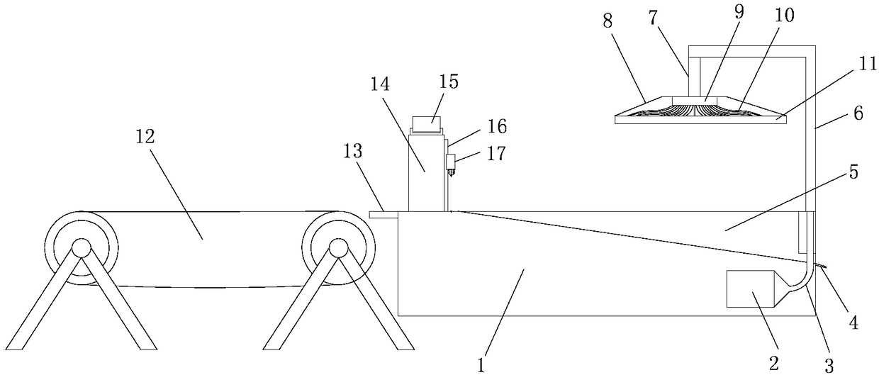
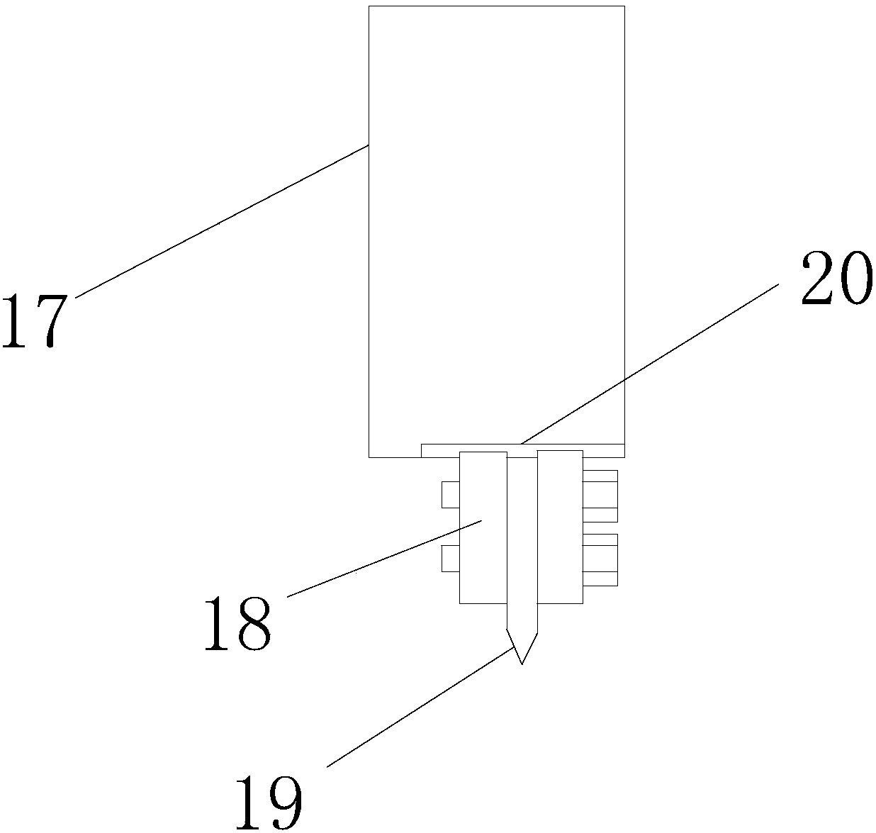
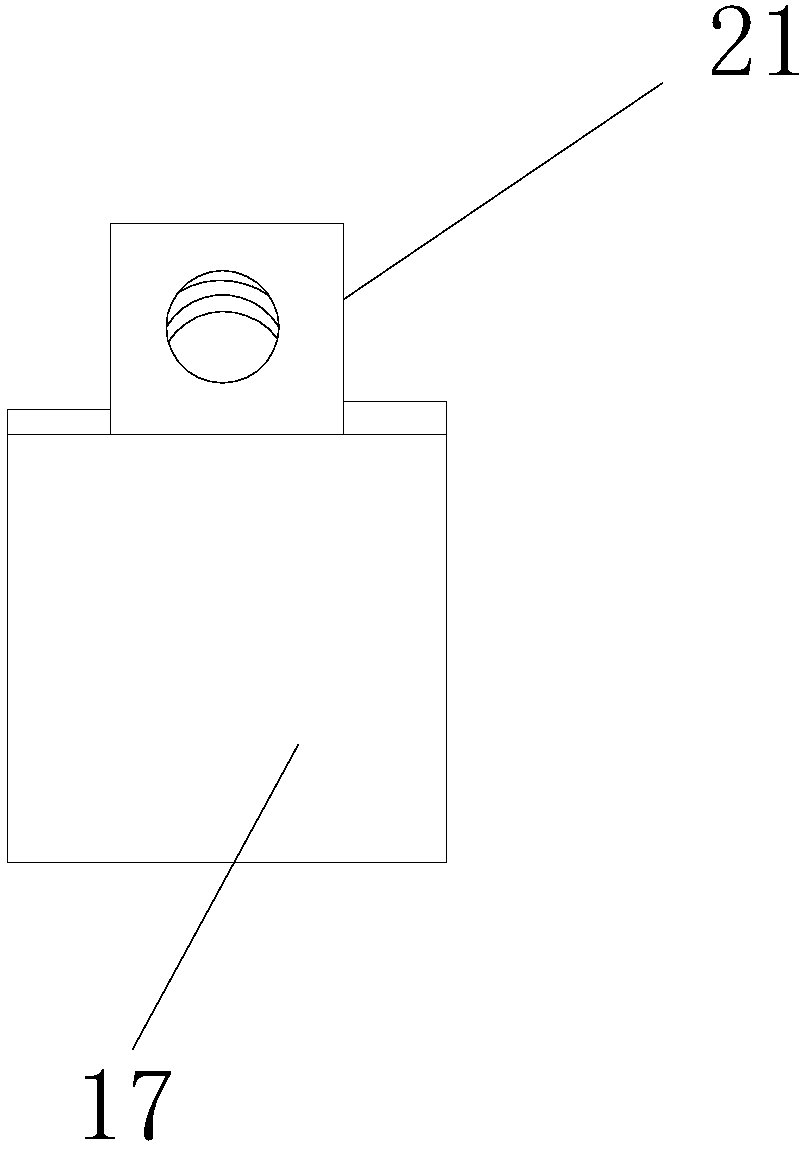
[0020] refer to Figure 1-5 , an automatic cutting device for backlight die-cutting and discharging, comprising a workbench 1 and a conveyor belt 12, one end of the workbench 1 is provided with a conveyor belt 12, the workbench 1 is a cuboid structure, and the end of the workbench 1 is close to the conveyor belt 12 Side upper part is welded with connecting plate 13, and connecting plate 13 is used for connecting the space between workbench 1 and conveyer belt 12, and described workbench 1 is welded with support column 14 near one end top of conveyer belt 12, and the side of described support column 14 is provided with There is a rectangular hole, the top of the suppo...


PUM


Abstract

The invention discloses a backlight source die-cutting discharge automatic cutting device. The backlight source die-cutting discharge automatic cutting device comprises a workbench and a conveyor belt, wherein the conveyor belt is arranged at one end of the workbench. The backlight source die-cutting discharge automatic cutting device is characterized in that the workbench is of a cuboid structure, a supporting column is welded at the top of one end, close to the conveyor belt, of the workbench, the bottom of a connecting block is provided with a second sliding rail, the top of one clamping plate is welded on the second sliding rail, the top of the other clamping plate is in sliding connection with the second sliding rail, a cutting knife is fixed between the two clamping plates, the sideface of the workbench is fixedly provided with an air suction fan, the air suction end of the air suction fan is connected with a pipeline, an L-shaped supporting rod is welded to one side, away fromthe supporting column, of the workbench, a connecting rod is welded to the tail end of the L-shaped supporting rod, the lower end of the connecting rod is fixedly provided with an air suction disc, and the air suction disc is of a circular truncated cone-shaped structure. According to the backlight source die-cutting discharge automatic cutting device, through the design of the air suction disc, dust above the workbench can be absorbed, and the influence of the dust on an optical module of the workbench is prevented.

Description

technical field [0001] The invention relates to the technical field of cutting devices, in particular to an automatic cutting device for backlight die-cutting and discharging. Background technique [0002] Backlight (BackLight) is a light source located behind the liquid crystal display (LCD), and its luminous effect will directly affect the visual effect of the liquid crystal display module (LCM). The LCD itself does not emit light, it displays graphics or the result of its modulation of light. The backlight is mainly composed of a light source, a light guide plate, an optical module, and structural parts. [0003] In the production process, optical dies need to be cut. During the cutting process, try to ensure that the cutting process is clean to prevent dust from falling on the dies and avoid unnecessary troubles. The existing cutting equipment is generally saw gear or water Knife cutting, saw gear cutting is bound to have a lot of dust. Patent No. CN 205183901 U propo...

Claims


Application Information

Patent Timeline
Patent Type & Authority Applications(China)
IPC IPC(8): B26D1/08B26D5/08B26D7/18B26D7/06B26D7/32
CPCB26D1/085B26D5/08B26D7/0625B26D7/1863B26D7/32B26D2007/322
Inventor 赵圣铭
Owner YANCHENG SANDING ELECTRONICS TECH CO LTD
Why Eureka
Try Eureka