3D printing method and equipment

A 3D printing and printing-oriented technology, applied in the field of 3D printing, can solve the problems of long time-consuming printing and time-consuming growth.

Active Publication Date: 2019-02-05
ZHUHAI SAILNER 3D TECH CO LTD
View PDF7 Cites 3 Cited by
  • Summary
  • Abstract
  • Description
  • Claims
  • Application Information

AI Technical Summary

Problems solved by technology

[0004] However, in the current 3D printing technology, since the print head needs to move back and forth when printing each layer of data, depending on the size of

Method used


Image

  • 3D printing method and equipment
  • 3D printing method and equipment
  • 3D printing method and equipment

Examples


Embodiment 1

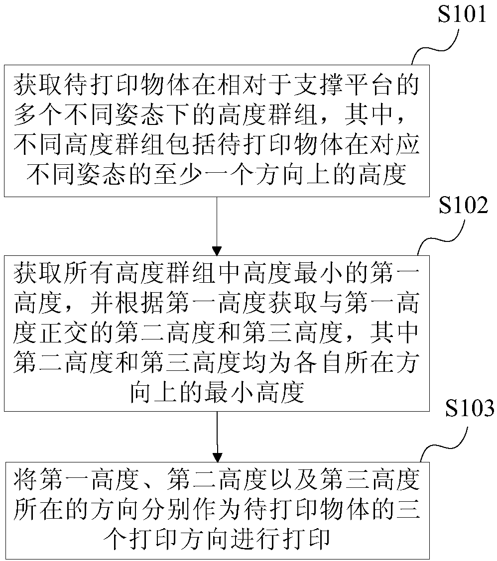
[0028] figure 1 It is a schematic flow chart of a 3D printing method provided in Embodiment 1 of the present invention. Such as figure 1 As shown, the 3D printing method provided in this embodiment specifically includes the following steps:

[0029] S101. Acquire height groups of the object to be printed in multiple different postures relative to the support platform, wherein the different height groups include heights of the object to be printed in at least one direction corresponding to different postures.

[0030] Wherein, the object to be printed can have a regular or irregular shape. In the traditional 3D printing process, the placement posture of the object to be printed is generally determined according to the distribution of its center of gravity, such as vertical or flat placement. However, in this embodiment, multiple possible postures of the object to be printed on the support platform need to be obtained, that is, multiple different orientations that the object t...

Embodiment 2

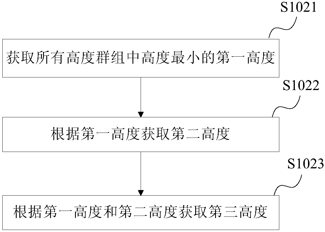
[0040] After obtaining multiple height groups of the object to be printed, when obtaining the first height, the second height, and the third height in the height group, you can set priorities for different heights, and obtain the first height in order according to the priority , the second height and the third height. figure 2 It is a schematic flowchart of obtaining the first height, the second height and the third height in multiple height groups of the object to be printed provided by the second embodiment of the present invention. Such as figure 2 As shown, specifically, in step S102, specifically, the following sub-steps may be included:

[0041] S1021. Obtain the first height with the smallest height among all height groups.

[0042] Specifically, the first height is the smallest height among all height groups, so its direction can match the direction with the slowest printing speed when printing the object to be printed, so as to save the consumption of printing tim...

Embodiment 3

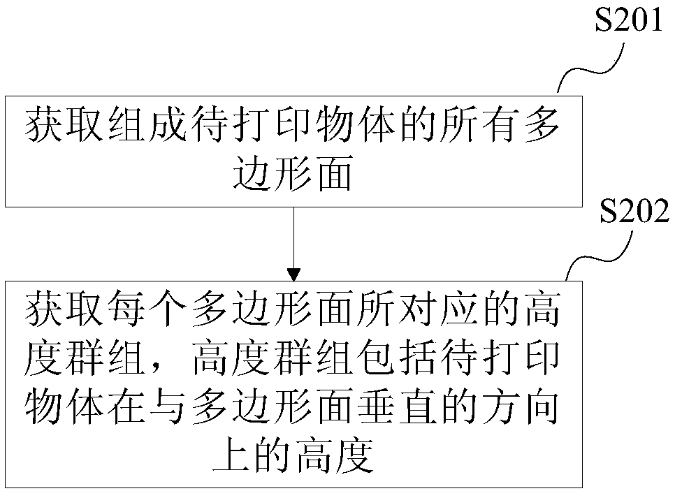
[0053] On the basis of the second embodiment above, when obtaining multiple height groups of the object to be printed, and obtaining the first height, the second height and the third height from these height groups, the model of the object to be printed can be Grid division is performed on the grid, and the directions of the first height, the second height and the third height are determined according to the direction of each grid unit. image 3 It is a schematic flow chart of acquiring height groups of objects to be printed provided by Embodiment 3 of the present invention. Such as image 3 As shown, the steps of obtaining the height group of the object to be printed in multiple different postures relative to the support platform include:

[0054] S201. Obtain all polygonal faces composing the object to be printed.

[0055] Wherein, the model of the object to be printed can be composed of multiple polygonal surfaces, and the area size and quantity of the polygonal surfaces ...


PUM


Abstract

The invention provides a 3D printing method and equipment. The 3D printing method comprises the steps that height groups of a to-be-printed object in multiple different poses relative to a supportingplatform is obtained, wherein the different height groups comprise the heights of the to-be-printed object in at least one direction corresponding to the different poses; the smallest first height inthe height groups is obtained, and the second height and the third height which are orthogonal with the first height are obtained according to the first height, wherein the second height and the thirdheight are the smallest heights in the self directions; and the directions where the first height, the second height and the third height are located are used as three printing directions of the to-be-printed object for printing. The high printing speed can be achieved.

Description

technical field [0001] The invention relates to the field of 3D printing, in particular to a 3D printing method and equipment. Background technique [0002] 3D printing (3D Printing, 3DP) technology, also known as additive manufacturing (Additive Manufacturing, AM) technology or rapid prototyping (Rapid Prototyping, RP) technology, is based on the principle of discrete accumulation, by layering the model, on the support platform Layer-by-layer printing, and then multi-layer stacking to finally make the three-dimensional structure technology of the target 3D object, including Fused Deposition Modeling (FDM) technology, Stereo Lithography Apparatus (SLA) technology, Selective Laser Sintering (Selective Laser Sintering) , SLA) technology, Digital Light Processing (Digital Light Processing, DLP) technology, layered object manufacturing (Laminated Object Manufacturing, LOM) technology, inkjet technology, etc. [0003] In the commonly used 3D printing technology, the 3D printing ...

Claims


Application Information

Patent Timeline
IPC IPC(8): B29C64/393B29C64/20B33Y50/02B33Y10/00B33Y30/00
CPCB33Y10/00B33Y50/02B29C64/393G06F30/20G06F2113/10G06F2119/18Y02P90/02B33Y30/00B29C64/20
Inventor 向东清陈伟谢林庭
Owner ZHUHAI SAILNER 3D TECH CO LTD
Why Eureka
Try Eureka