Marking method for circular tube printing object overprinting starting point
A marking method and substrate technology, applied in printing, printing devices and other directions, can solve problems such as low overprinting accuracy, and achieve the effects of improving overprinting accuracy, saving production man-hours, and high implementation efficiency
- Summary
- Abstract
- Description
- Claims
- Application Information
AI Technical Summary
Problems solved by technology
Method used
Image
Examples
specific Embodiment approach 1
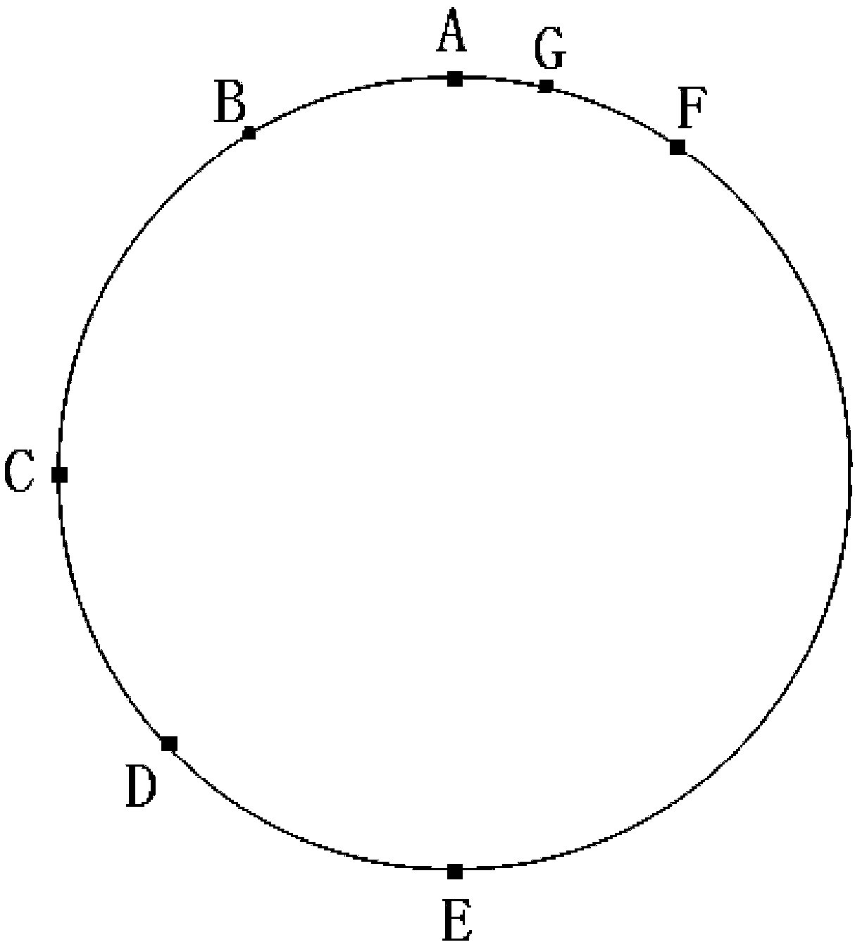
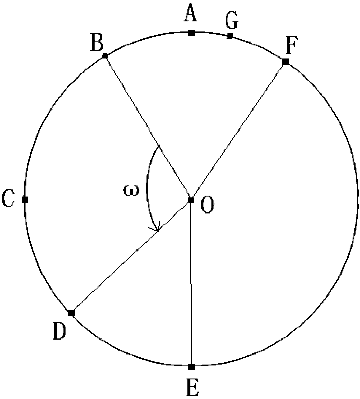
[0018] Specific implementation mode one: as figure 1 , figure 2 As shown, the method for marking the overprint starting point of a circular tubular substrate given in this embodiment specifically includes:
[0019] When the first color is printed on the circular tubular substrate, the sensor is used for ring detection, and a specific point is selected from the detected points of the first color as the overprinting starting point for marking;
[0020] The sensor in this embodiment can be a color mark sensor, an optical fiber sensor and a laser sensor.
[0021] For the color printing of circular tubular substrates, it is necessary to set N printing units according to the number of colors N of the printing pattern to print different colors sequentially. The starting point of N color printing must be consistent with the starting point of the first color printing. Therefore, usually after the first color is printed, the starting point is selected by the sensor for marking, and ...
specific Embodiment approach 2
[0033] Embodiment 2: This embodiment is different from Embodiment 1 in that 1°≤ω≤359°. The circle of the tubular substrate is 360°, and 1°~359° can avoid the situation that the two points obtained are actually the same point due to the influence of error or servo motor delay (the delay is very small and can be ignored).
[0034] Other steps and parameters are the same as those in the first embodiment.
specific Embodiment approach 3
[0035] Embodiment 3: This embodiment is different from Embodiment 1 or Embodiment 2 in that ω is selected as 90°. The line connecting the two points and the center of the circular detection circle is perpendicular to each other, and a special angle is selected to facilitate identification and calculation.
[0036] Other steps and parameters are the same as those in Embodiment 1 or 2.
PUM
 Abstract
Description
Claims
Application Information
 - R&D
- Intellectual Property
- Life Sciences
- Materials
- Tech Scout
- Unparalleled Data Quality
- Higher Quality Content
- 60% Fewer Hallucinations
Browse by: Latest US Patents, China's latest patents, Technical Efficacy Thesaurus, Application Domain, Technology Topic, Popular Technical Reports.
© 2025 PatSnap. All rights reserved.Legal|Privacy policy|Modern Slavery Act Transparency Statement|Sitemap|About US| Contact US: help@patsnap.com


