
Hardware accessory drying device

A technology for drying devices and accessories, applied in the directions of drying, drying machine, drying gas arrangement, etc., can solve the problems of long time required for drying, affecting the operation of mechanical equipment, reducing drying work efficiency, etc. Simple, work efficiency improvement, and the effect of reducing the amount of handling

Inactive Publication Date: 2019-02-05
开平市红火卫浴有限公司
View PDF0 Cites 4 Cited by
  • Summary
  • Abstract
  • Description
  • Claims
  • Application Information

AI Technical Summary

Problems solved by technology

In large-scale mechanical equipment, some precision mechanical parts are generally composed of small hardware parts. It is only under the joint action of these hardware parts that large-scale mechanical equipment can be safely operated and produced. However, these small After a long time of use of hardware parts, the surface will be covered with a layer of dust, which not only affects the operation of mechanical equipment, but also reduces work efficiency. Therefore, these parts will be removed for cleaning at regular intervals, and then need to be cleaned The cleaned hardware accessories are dried, and the existing drying device is more cumbersome to operate, and it takes a long time to dry, and it cannot be effectively dried in a short time, thus greatly reducing the drying efficiency.

Method used


Image

  • Hardware accessory drying device
  • Hardware accessory drying device
  • Hardware accessory drying device

Examples


Embodiment Construction

[0018] Below in conjunction with accompanying drawing and specific embodiment the present invention is described in further detail:

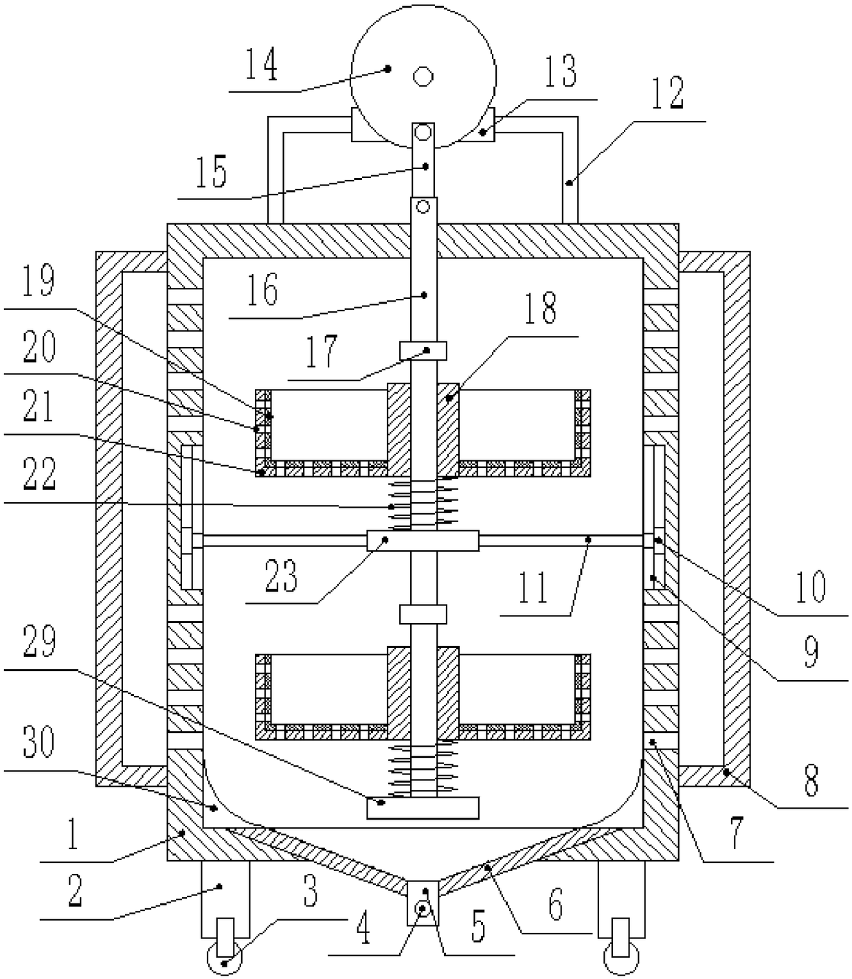
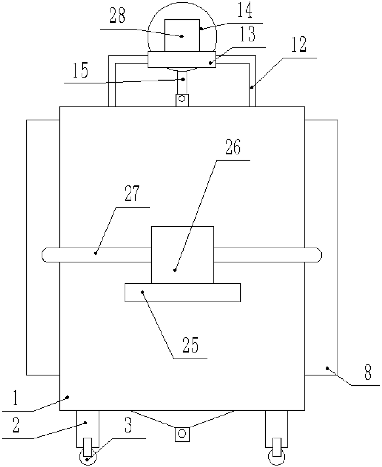
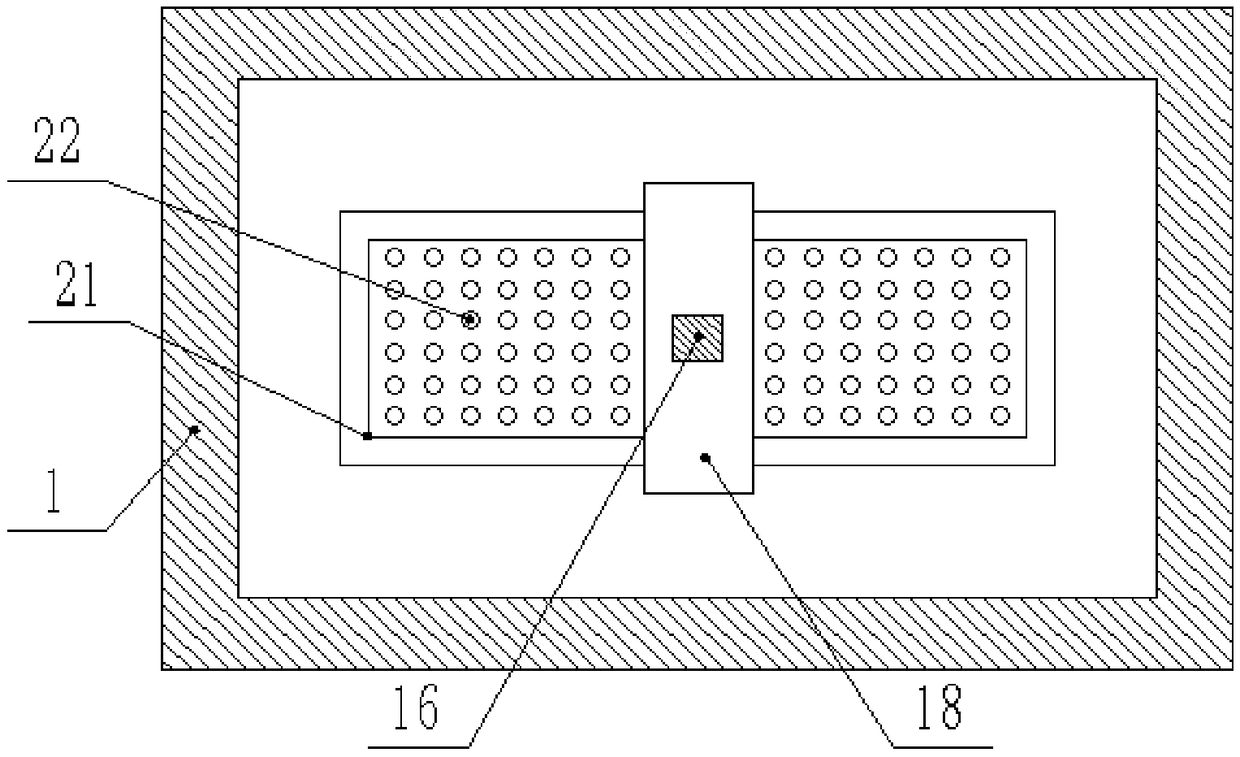
[0019] Such as figure 1 , figure 2 , image 3 , Figure 4 As shown, a drying device for hardware accessories includes a box body 1, legs 2 are fixedly connected to the four corners of the bottom end of the box body 1, wheels 3 are fixedly installed on the bottom end of the legs 2, and the box body 1 Both side walls of the body 1 are provided with a cover body 8, and one side of the box body 1 is provided with a box door 24, and the box door 24 is hingedly connected with the box body 1, and the box door 24 is provided with a plurality of The air outlet 31, the other side wall of the box body 1 is fixedly connected with a second horizontal plate 25, the top surface of the second horizontal plate 25 is fixedly connected with a hot air blower 26, and the output end of the hot air blower 26 The middle part of the U-shaped pipe 27 is fixedly conn...


PUM


Abstract

The invention discloses a hardware accessory drying device. The hardware accessory drying device comprises a box. The four corners of the bottom end of the box are fixedly connected with landing legs.Wheels are fixedly arranged at the bottom ends of the landing legs. Covers are arranged on the two side walls of the box, and a box door is arranged on one side of the box. The hardware accessory drying device is simple in structure; a rubber layer is arranged on the inner wall of a square groove, and abrasion caused by collisions between hardware accessories and the square groove can be effectively avoided. The device can dry more hardware accessories or multiple kinds of hardware accessories at the same time, and through batched drying, the work efficiency is effectively improved. Under running of a motor, the hardware accessories in the square groove slightly bump on a sliding rod under the action of springs, and the hardware accessories are effectively protected through slight bumping. Meanwhile, hot air can comprehensively and effectively dry the hardware accessories; and through the arrangement of the wheels, the carrying amount of the hardware accessories can be effectively reduced, the hardware accessories are conveniently dried, and the work efficiency is effectively improved.

Description

technical field [0001] The invention relates to the technical field of hardware accessories, in particular to a drying device for hardware accessories. Background technique [0002] With the development of science and technology, society progresses. At present, all kinds of hardware products have been deeply integrated into our lives, which facilitates our lives. In large-scale mechanical equipment, some precision mechanical parts are generally composed of small hardware parts. It is only under the joint action of these hardware parts that large-scale mechanical equipment can be safely operated and produced. However, these small After a long time of use of hardware parts, the surface will be covered with a layer of dust, which not only affects the operation of mechanical equipment, but also reduces work efficiency. Therefore, these parts will be removed for cleaning at regular intervals, and then need to be cleaned The cleaned hardware accessories are dried, but the existi...

Claims


Application Information

Patent Timeline
Patent Type & Authority Applications(China)
IPC IPC(8): F26B11/00F26B11/18F26B21/00
CPCF26B11/00F26B11/18F26B21/00
Inventor 付江波
Owner 开平市红火卫浴有限公司
Learn More