Method and system for compensating gravity center deviation of unmanned aerial vehicle

A technology of center of gravity offset and compensation method, applied in control/regulation systems, non-electric variable control, instruments, etc., can solve the problems of inconsistent geometric center, unsatisfactory control effect, affecting user flight experience and operability, etc.

Active Publication Date: 2019-02-05
SHENZHEN SPROCOMM TECH CO LTD
View PDF10 Cites 4 Cited by
  • Summary
  • Abstract
  • Description
  • Claims
  • Application Information

AI Technical Summary

Problems solved by technology

[0002] In the prior art, the unmanned aerial vehicle with a gimbal will have the situation that the center of gravity of the aircraft is inconsistent with the geometric center of the aircraft body, and the resulting deviation of the center of gravity will lead to unsatisfactory control effects, especially in manual mode. The aircraft will obviously drift in the direction of the center of gravity offset, which greatly affects the flying experience and operability of users, especially novices

Method used


Image

  • Method and system for compensating gravity center deviation of unmanned aerial vehicle
  • Method and system for compensating gravity center deviation of unmanned aerial vehicle
  • Method and system for compensating gravity center deviation of unmanned aerial vehicle

Examples


Embodiment 1

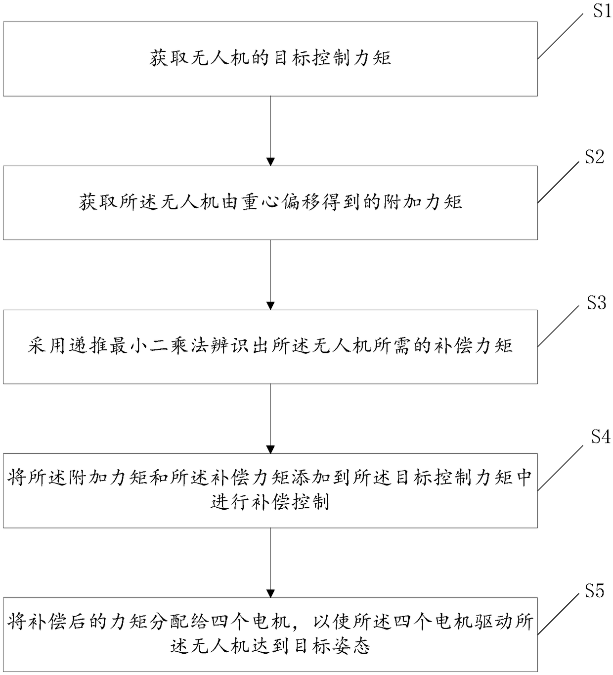
[0066] The embodiment of the present invention provides a compensation method for center of gravity offset of UAV, see figure 1 , the method includes:

[0067] S1. Obtain the target control moment of the UAV;

[0068] S2. Obtain the additional moment obtained by the center of gravity offset of the drone;

[0069] S3. Using the recursive least squares method to identify the compensation torque required by the drone;

[0070] S4. Add the additional torque and the compensation torque to the target control torque to perform compensation control;

[0071] S5. Distributing the compensated torque to the four motors, so that the four motors drive the UAV to reach the target attitude.

[0072] It should be noted that after the center of gravity of the UAV is shifted, the additional moment obtained by the UAV from the shift of the center of gravity and the target control moment of the UAV are obtained, and the compensation required by the UAV is obtained by the recursive least square...

Embodiment 2

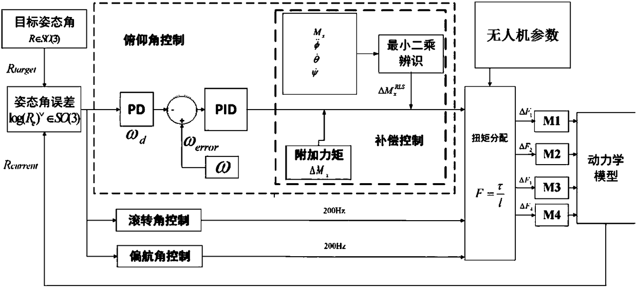
[0125] An embodiment of the present invention provides a compensation system for the offset of the center of gravity of the UAV, which can realize all the processes of the compensation method for the offset of the center of gravity of the UAV, see Figure 6 , the compensation system for the deviation of the center of gravity of the drone includes:

[0126] The first obtaining module 1 is used to obtain the target control torque of the UAV;

[0127] The second acquisition module 2 is used to acquire the additional moment obtained by the offset of the center of gravity of the drone;

[0128] The identification module 3 is used to identify the compensation torque required by the UAV by using the recursive least squares method;

[0129] a compensation module 4, configured to add the additional torque and the compensation torque to the target control torque to perform compensation control; and,

[0130] The distribution module 5 is configured to distribute the compensated torque ...


PUM


Abstract

The invention discloses a method for compensating a gravity center deviation of an unmanned aerial vehicle, and further discloses a system for compensating the gravity center deviation of the unmannedaerial vehicle. The method comprises the steps that the target control moment of the unmanned aerial vehicle is obtained; the additional torque, obtained by the gravity center deviation, of the unmanned aerial vehicle is obtained; the compensation torque required by the unmanned aerial vehicle is identified through a recursive least-squares method; the additional torque and the compensation torque are added into the target control moment for compensation control; and the compensated torque is assigned to four motors to enable the four motors to drive the unmanned aerial vehicle to reach to the target attitude. The gravity center deviation of the unmanned aerial vehicle can be subjected to compensation control, the dynamic performance and anti-jamming capability of the unmanned aerial vehicle are effectively improved, and then the flight experience of a user is improved.

Description

technical field [0001] The invention relates to the technical field of unmanned aerial vehicles, in particular to a compensation method and system for center-of-gravity offset of an unmanned aerial vehicle. Background technique [0002] In the prior art, the unmanned aerial vehicle with a gimbal will have the situation that the center of gravity of the aircraft is inconsistent with the geometric center of the aircraft body, and the resulting deviation of the center of gravity will lead to unsatisfactory control effects, especially in manual mode. The aircraft will obviously drift in the direction of the center of gravity offset, which greatly affects the flying experience and operability of users, especially novices. Therefore, it is necessary to accurately identify and compensate the UAV center of gravity deviation. Contents of the invention [0003] Aiming at the problems existing in the prior art, the present invention provides a compensation method and system for cent...

Claims


Application Information

Patent Timeline
Patent Type & Authority Applications(China)
IPC IPC(8): G05D1/08
CPCG05D1/0825
Inventor 康腾黄涛刘国良费鹏
Owner SHENZHEN SPROCOMM TECH CO LTD
Why Eureka
Try Eureka