Liquid material discharge device, coating device and coating method thereof
A liquid material and control device technology, which is applied to the surface coating liquid device, valve device, coating, etc., can solve the problems of uneven discharge volume, uncertain coating shape or coating position, splashing, etc., to achieve Good responsiveness, prevents scattered drawing lines, and stable ejection effect
- Summary
- Abstract
- Description
- Claims
- Application Information
AI Technical Summary
Problems solved by technology
Method used
Image
Examples
no. 1 approach 》
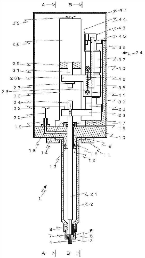
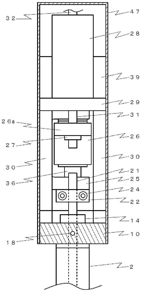
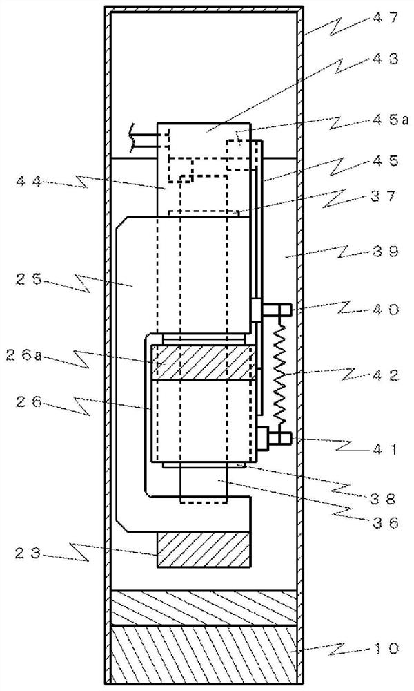
[0052] The discharge device 1 according to the first embodiment of the present invention is of a type in which the communication hole 7 of the valve seat 6 is opened by the upward movement of the valve stem 21 to discharge the liquid material, and is closed by the downward movement of the valve stem 21 to stop the discharge. The discharge device is mounted on the coating device 101 in a negative pressure space and used. In the discharge device 1 , the discharge control device 33 controls the operation of the electric actuator 28 to adjust the speed or acceleration of the valve rod 21 , thereby preventing the generation of air bubbles. In addition, the position detection mechanism 34 for detecting the contact position of the valve stem 21 and the valve seat 6 is provided, so that even if the valve stem 21 or the valve seat 6 is worn, the communication hole 7 of the valve seat 6 can be reliably closed. .
[0053] Hereinafter, first, the configuration of the discharge device 1 w...
no. 2 approach 》
[0102] Figure 8 The liquid material discharge device 1 of the second embodiment shown differs from the first embodiment mainly in that the storage container 2 is not a syringe through which the valve rod 21 is inserted, but a syringe connected via an extending member 60 . Hereinafter, differences from the first embodiment will be mainly described, and descriptions of common elements may be omitted.
[0103] The stem driving system (the part above the main body lower member 10 ) inside the hood 47 is the same as that of the first embodiment. The actuator 28 reciprocates the actuator rod 31 up and down, so that the valve rod 21 reciprocates up and down via the drive transmission member 26 , the upper slider 37 and the lower slider 38 .
[0104] The main body lower member 10 of the second embodiment is different from the first embodiment in that it is continuous with the extending portion 58 extending downward. Wherein, the main body lower member 10 and the extension part 58 m...
no. 3 approach 》
[0117] Figure 9 and Figure 10 The liquid material discharge device 1 of the third embodiment shown mainly includes an outer frame 201, an inner frame 218, a sensor 43, and a detection plate 45 mounted on the inner frame, and has a structure in which the sensor 43 detects that the inner frame moves up and down. The aspect is different from the first embodiment. Hereinafter, the same symbols are assigned to the same elements as those of the first embodiment, and explanations may be omitted.
[0118]
[0119] Figure 9 A partially cutaway front view of the discharge device according to the third embodiment is shown in . Figure 10 displayed in Figure 9 C-C arrow view in . Furthermore, sometimes the Figure 10 In , the actuator side is referred to as "back", the opposite side across the central axis is referred to as "front", and the left and right surfaces between the rear and front are referred to as "side".
[0120] The valve rod 21 of the third embodiment is a line...
PUM
 Abstract
Description
Claims
Application Information
 - R&D
- Intellectual Property
- Life Sciences
- Materials
- Tech Scout
- Unparalleled Data Quality
- Higher Quality Content
- 60% Fewer Hallucinations
Browse by: Latest US Patents, China's latest patents, Technical Efficacy Thesaurus, Application Domain, Technology Topic, Popular Technical Reports.
© 2025 PatSnap. All rights reserved.Legal|Privacy policy|Modern Slavery Act Transparency Statement|Sitemap|About US| Contact US: help@patsnap.com


