Portable laparoscopic device for children
A laparoscopic and portable technology, applied in laparoscopy, endoscopy, medical science, etc., can solve the problems of inseparability, unfavorable carrying, difficult operation, etc., and achieve automatic fine control, high operation stability, and flexible operation structure Effect
- Summary
- Abstract
- Description
- Claims
- Application Information
AI Technical Summary
Problems solved by technology
Method used
Image
Examples
Embodiment 1
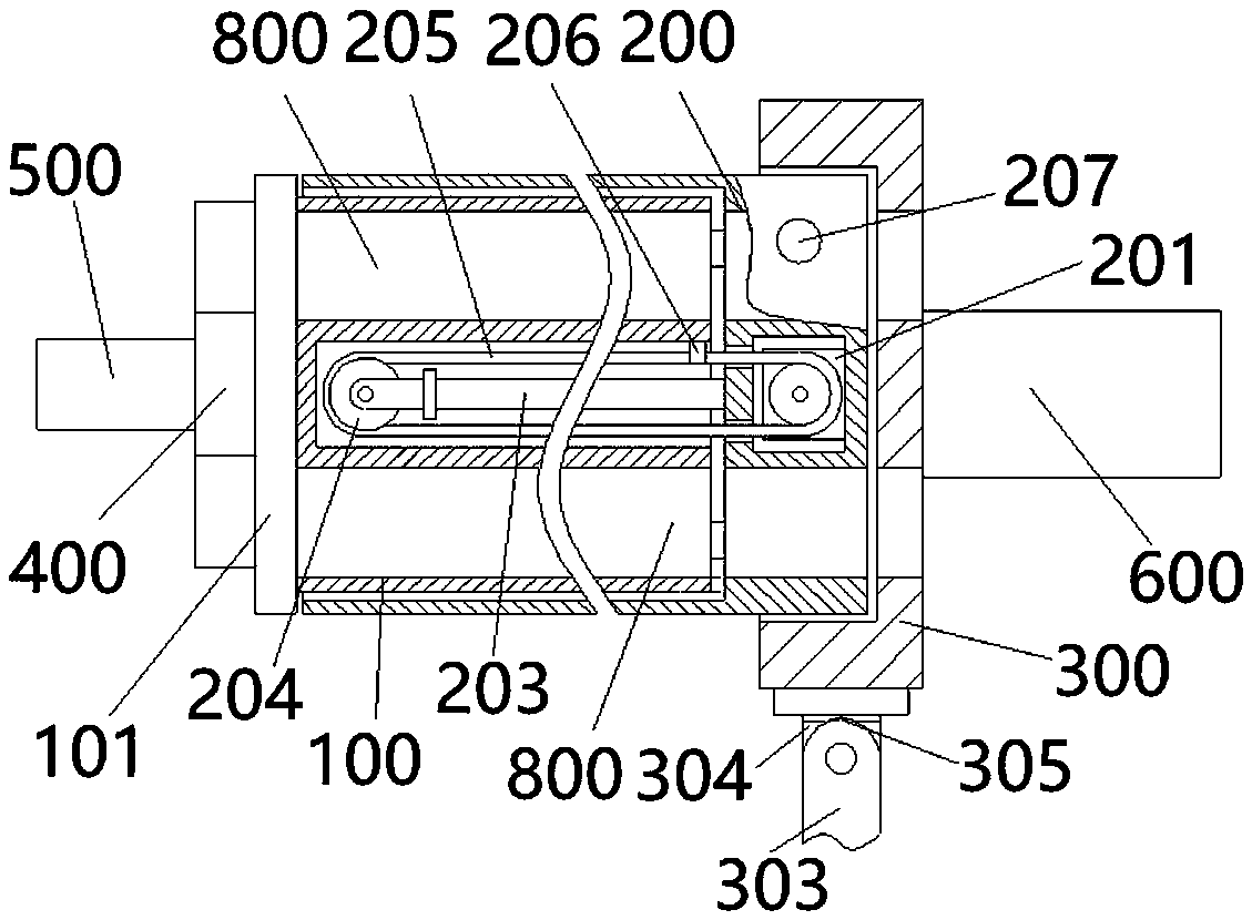
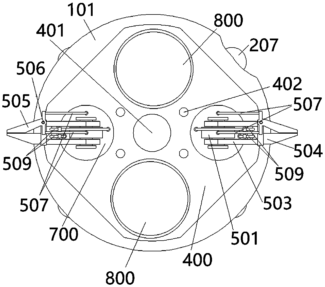
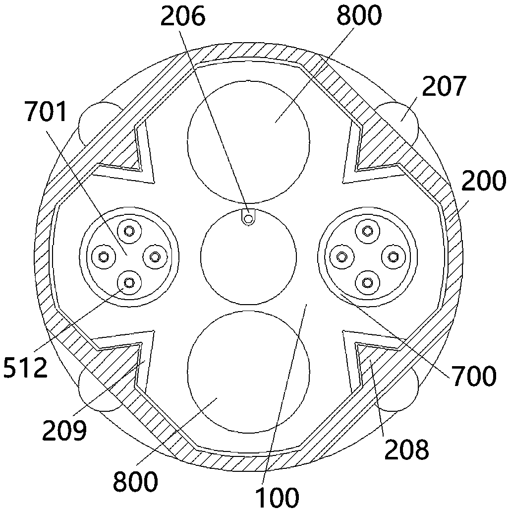
[0055] see Figure 1-8 , The portable laparoscopy device for children in this embodiment mainly includes an inner sleeve 100 , an outer sleeve 200 , an assembly seat 300 , an assembly head 400 , an action assembly 500 and a drive assembly 600 . Wherein, the left end of the outer cover 200 is open, and the inner cover 100 is sleeved in the outer cover 200 from the opening end of the outer cover 200, and is slidably connected with the outer cover 200; On one side, the limiting plate 101 is installed with the assembly head 400 on the other side, and the limiting plate 101 is used to limit the sliding range of the inner sleeve 100 relative to the outer sleeve 200 . The outer end of the assembly head 400 is equipped with an action assembly 500, and the action assembly 500 is used to clamp the tissue of the surgical site; the right end of the overcoat 200 is detachably installed with an assembly seat 300, and the outer end of the assembly seat 300 is installed with a drive assembly ...
Embodiment 2
[0066] In the present invention, the inner sleeve 100 is slidably connected to the outer sleeve 200 , and the outer sleeve 200 is detachably connected to the assembly seat 300 . This embodiment is a preferred solution of Embodiment 1, and specific connection methods of the inner sleeve 100 and the outer sleeve 200 , and the outer sleeve 200 and the assembly seat 300 will be provided.
[0067] In this embodiment, the jacket 200 is connected to the assembly seat 300 in a clamping manner. see image 3 , Figure 4 and Figure 8 , the outside of the right part of the jacket 200 is fixedly installed with a number of clip beads 207 equidistantly arranged around the edge of the jacket 200; A clamping bracket 302 matching the clamping beads 207 is mounted on the inner side, and the clamping connection between the jacket 200 and the assembly seat 300 is realized by installing the clamping beads 207 on the corresponding clamping frame 302 .
[0068] In this embodiment, the sliding co...
Embodiment 3
[0070] This embodiment is also a preferred solution of Embodiment 1. For convenience, a handle 303 for holding is installed at the bottom of the assembly base 300 in this embodiment. see figure 1 and Figure 6A handle base 304 is installed at the bottom of the assembly base 300, and a handle 303 is rotatably connected to the lower part of the handle base 304. Specifically, a protruding head 305 is provided at the top of the handle 303, and a slot matching the protruding head 305 is provided at the lower part of the handle base 304; the handle 303 is rotationally connected to the handle base 304 by putting the protruding head 305 into the slot. superior. When the handle 303 needs to be used, the handle 303 is rotated to open; when the handle 303 is not needed to be used, the handle 303 is rotated and folded.
PUM
 Abstract
Description
Claims
Application Information
 - R&D
- Intellectual Property
- Life Sciences
- Materials
- Tech Scout
- Unparalleled Data Quality
- Higher Quality Content
- 60% Fewer Hallucinations
Browse by: Latest US Patents, China's latest patents, Technical Efficacy Thesaurus, Application Domain, Technology Topic, Popular Technical Reports.
© 2025 PatSnap. All rights reserved.Legal|Privacy policy|Modern Slavery Act Transparency Statement|Sitemap|About US| Contact US: help@patsnap.com


