
High-efficient energy-saving gas-liquid separator

A gas-liquid separator, high-efficiency and energy-saving technology, used in gas fuel, petroleum industry, fuel and other directions, can solve problems such as safety accidents, difficult utilization, liquid pipeline blockage, etc., to avoid U-shaped pipe blockage and improve the effect.

Inactive Publication Date: 2019-02-12
西安交通工程学院
View PDF5 Cites 5 Cited by
  • Summary
  • Abstract
  • Description
  • Claims
  • Application Information

AI Technical Summary

Problems solved by technology

[0003] When the existing gas-liquid separator performs gas-liquid separation of natural gas, the separated gas is easily entrained in the separated liquid and discharged together with the separated liquid, resulting in incomplete gas-liquid separation, and the extracted natural gas At the same time, it also contains some solid impurities, and this part of solid impurities will be separated out along with the liquid. The existence of this part of impurities can easily cause blockage of the liquid pipeline when the liquid is discharged. After the pipeline is blocked, the liquid cannot be discharged in time. It is easy to cause safety accidents. In addition, the separation speed of the existing gas-liquid separator is very slow and it is difficult to effectively use it.

Method used


Image

  • High-efficient energy-saving gas-liquid separator

Examples


Embodiment Construction

[0025] The technical solutions in the embodiments of the present invention will be clearly and completely described below with reference to the accompanying drawings in the embodiments of the present invention. Obviously, the described embodiments are only a part of the embodiments of the present invention, but not all of the embodiments. Based on the embodiments of the present invention, all other embodiments obtained by those of ordinary skill in the art without creative efforts shall fall within the protection scope of the present invention.

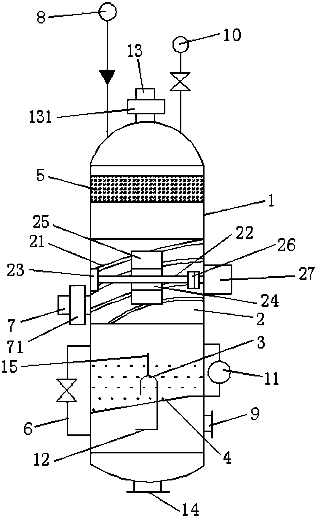
[0026] see figure 1, the present invention provides a technical solution: a high-efficiency and energy-saving gas-liquid separator, comprising a gas-liquid separation tank 1, a gas-liquid separator 2 is arranged inside the gas-liquid separation tank 1, and the gas-liquid separator 2 separates the The inner space of the gas-liquid separation tank 1 is divided into a gas collection chamber and a liquid collection chamber, the gas collec...


PUM


Abstract

The invention discloses a high-efficient energy-saving gas-liquid separator, which comprises a gas-liquid separation tank, a gas-liquid separator body is arranged in the gas-liquid separation tank, the gas-liquid separator body divides an internal space of the gas-liquid separation tank into a gas collection chamber and a liquid collection chamber, a liquid inlet pipe is arranged on the gas-liquidseparation tank, an exhaust pipe is arranged on the top of the gas-liquid separation tank, a drain pipe is arranged on the bottom of the gas-liquid separation tank , a projecting metal strip is mounted on the internal wall of the gas-liquid separator body, a horizontally arranged agitating rod is arranged in the gas-liquid separator body, clamping plates are welded on the agitating rod, moreover,agitating blades are connected to the clamping plates through bolts, a liquid collection plate is arranged in the liquid collection chamber, the liquid collection plate divides the liquid collectionchamber into an upper liquid collection chamber and a lower liquid discharge chamber, an inverted U-shaped pipe is arranged in the liquid collection chamber, one end of the inverted U-shaped pipe is arranged over the liquid collection plate, and the other end runs through the liquid collection plate and extends into the liquid discharge chamber. According to the high-efficient energy-saving gas-liquid separator provided by the invention, as gas-liquid separation is carried out, the whole high-efficient energy-saving gas-liquid separator can quickly separate gas and liquid, and has the advantages of good separation effect and resource saving.

Description

technical field [0001] The invention relates to the technical field of gas-liquid separation, in particular to a high-efficiency and energy-saving gas-liquid separator. Background technique [0002] Natural gas usually contains water and other impurities such as hydrogen sulfide, mercaptans, heavy hydrocarbon gas, etc. Among them, hydrogen sulfide, mercaptans, etc. are called "acidic" substances. Substances will dissolve in water to form weak acid, and the formation of weak acid will aggravate the corrosion of gas pipelines. Therefore, it is necessary to separate natural gas from gas and liquid to remove the water contained in natural gas. Gas-liquid separation is performed to remove water contained in natural gas. [0003] When the existing gas-liquid separator performs gas-liquid separation on natural gas, the separated gas is easily entrained in the separated liquid and discharged together with the separated liquid, resulting in incomplete gas-liquid separation, and in t...

Claims


Application Information

Patent Timeline
IPC IPC(8): C10L3/10
CPCC10L3/102
Inventor 康勇
Owner 西安交通工程学院
Learn More