High-strength impact-resistant aluminum plate

An impact-resistant, high-strength technology, applied in building materials, building components, buildings, etc., can solve problems such as the inability to cope with the impact of external forces on the cover plate

Inactive Publication Date: 2019-02-12
平湖市法埃斯铝制品有限公司
5 Cites 0 Cited by

AI-Extracted Technical Summary

Problems solved by technology

[0004] The above-mentioned mechanism realizes the cushioning of the cover plate by temporarily squeezing the air in the soft bag into the piston cylinder, but the soft bag is filled with air, and since the air is compressibl...

Abstract

The invention provides a high-strength impact-resistant aluminum plate, and belongs to the technical field of buildings. The high-strength impact-resistant aluminum plate solves the technical problemthat an existing high-strength impact-resistant aluminum plate cannot cope with external force impact resistance of a cover plate and the like. The high-strength impact-resistant aluminum plate comprises an aluminum bottom plate and an aluminum cover plate positioned on the bottom plate, a deformable buffer bag is arranged between the cover plate and the bottom plate, fixed frames are arranged onthe side, opposite to the cover plate, of the bottom plate, the cover plate can move back and forth in the direction of the bottom plate along the inner side surfaces of the fixed frames, the buffer bag is positioned in the fixed frames, the buffer bag is filled with buffer liquid, a plurality of sleeves are arranged in the buffer bag, one ends of the sleeves communicate with an inner cavity of the buffer bag, and the other ends of the sleeves are in a sealed state. Piston are arranged in the sleeves, the pistons can be driven by the buffer liquid to slide on the inner walls of the sleeves, springs are connected to the ends, sealed with the sleeves, of the pistons, and the sides, where the pistons are connected with the springs, of the inner part of the sleeves are filled with compressiblegas. The high-strength impact-resistant aluminum plate has the advantage that the aluminum plate can effectively resist the impact of external force.

Application Domain

Construction material

Technology Topic

PistonFixed frame +3

Image

  • High-strength impact-resistant aluminum plate

Examples

  • Experimental program(1)

Example Embodiment

[0015] The following are specific embodiments of the present invention in conjunction with the accompanying drawings to further describe the technical solutions of the present invention, but the present invention is not limited to these embodiments.
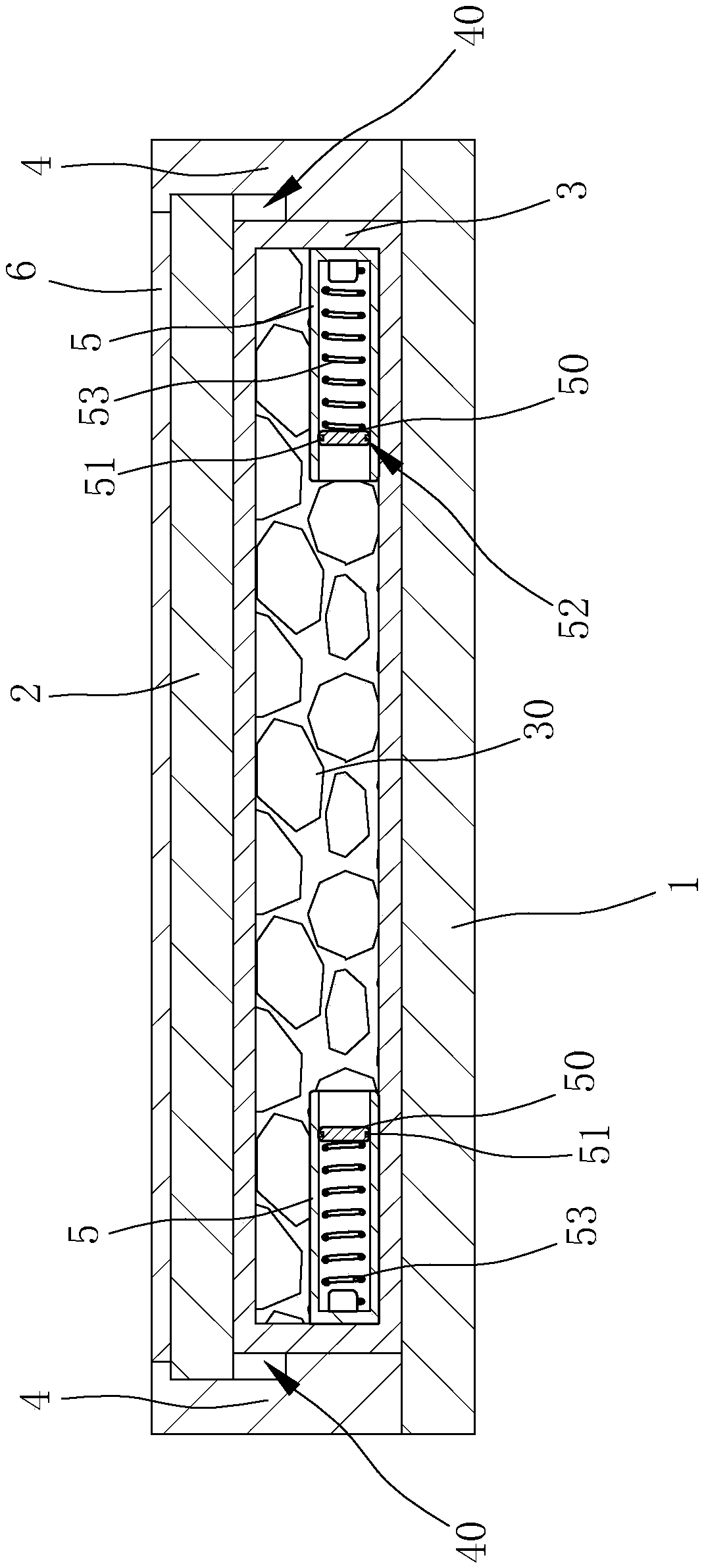
[0016] Such as figure 1 As shown, the high-strength impact-resistant aluminum plate includes an aluminum bottom plate 1 and an aluminum cover plate 2 located on the bottom plate 1. A deformable buffer bag 3 is provided between the cover plate 2 and the bottom plate 1, and the bottom plate 1 and the cover plate 2. A fixed frame 4 is provided on the opposite side near the side. The cover plate 2 can move back and forth along the inner side of the fixed frame 4 facing the bottom plate 1. The inner side of the fixed frame 4 is provided with a sliding groove 40 parallel to the cover plate 2. The width of the sliding groove 40 is greater than the thickness of the cover plate 2, the side of the cover plate 2 is pressed against the sliding groove 40 and the top surface of the cover plate 2 is pressed against the upper side wall of the sliding groove 40. The upper surface of the cover plate 2 is provided with a rubber pad 6, and the upper surface of the rubber pad 6 is flush with the upper surface of the fixing frame 4.
[0017] Such as figure 1 As shown, the buffer bag 3 is located in the cavity formed by the fixed frame 4, the buffer bag 3 is filled with buffer solution 30, the buffer bag 3 is provided with a number of sleeves 5, and one end of the sleeve 5 is connected to the inner cavity of the buffer bag 3. , The other end of the sleeve 5 is in a sealed state, the sleeve 5 is provided with a piston 50, the piston 50 can be driven by the buffer 30 to slide on the inner wall of the sleeve 5, the sealed end of the piston 50 and the sleeve 5 is connected with a spring 53, the sleeve Compressible gas is injected into the cylinder 5 on the side where the piston 50 and the spring 53 are connected. The side of the piston 50 is provided with a groove 52. The groove 52 is sleeved with a sealing ring 51. The piston 50 is in the sleeve through the sealing ring 51. 5 The inner wall seals and slides, and the outer side walls of the buffer bag 3 are all attached to the inner side wall of the fixed frame 4.
[0018] The upper surface of the cover plate 2 will receive a force towards the bottom plate 1 when it is impacted, so that the cover plate 2 will move toward the bottom plate 1. As the cover plate 2 and the bottom plate 1 have a buffer bag 3 between them, the cover plate 2 will be impacted The force is blocked by the bottom of the buffer bag 3. After the buffer bag 3 is subjected to an impact force, the buffer 30 is a liquid, and the liquid is not easily compressed. Therefore, the buffer 30 inside the buffer bag 3 will expand everywhere, due to the impact of the sleeve 5. One end is connected with the buffer 30, so the buffer 30 will squeeze the piston 50 in the sleeve 5, so that the impact force received by the buffer bag 3 is channeled to the spring 53 fixed on the piston 50, and finally the spring 53 Temporary deformation of the cover plate 2 is achieved by its own temporary deformation. After a period of deformation of the spring 53, the spring 53 will return to its original shape due to its own characteristics, so that the spring 53 pushes the piston 50 out of the sleeve 5 to the outer end. , And the buffer 30 originally located in the sleeve 5 will also return to the buffer bag 3 as the piston 50 returns to the buffer bag 3 to restore the buffer bag 3, and the cover plate 2 resting on the buffer bag 3 also moves to its original position. As a result, the cover plate 2 uses cushioning to obtain resistance to external impact.
[0019] The specific embodiments described herein are merely examples to illustrate the spirit of the present invention. Those skilled in the art to which the present invention pertains can make various modifications or additions to the specific embodiments described or use similar alternatives, but they will not deviate from the spirit of the present invention or exceed the definition of the appended claims. Range.

PUM

no PUM

Description & Claims & Application Information

We can also present the details of the Description, Claims and Application information to help users get a comprehensive understanding of the technical details of the patent, such as background art, summary of invention, brief description of drawings, description of embodiments, and other original content. On the other hand, users can also determine the specific scope of protection of the technology through the list of claims; as well as understand the changes in the life cycle of the technology with the presentation of the patent timeline. Login to view more.
Why Eureka
Try Eureka