Casing pipe type water conveying pipeline applied to crossing bridge and installation and construction method thereof

A technology for water pipelines and construction methods, which is applied in the direction of pipeline support, pipeline laying and maintenance, pipes/pipe joints/pipe fittings, etc., which can solve the problems of low construction efficiency, damage to plastic flexible pipes, and the lack of pressure resistance of the core layer, etc. problems, to achieve the effect of improving construction efficiency, ensuring stability, and preventing water seepage

Active Publication Date: 2019-02-12
CHINA HYDROPOWER ELEVENTH ENG BUREAU ZHENGZHOU CO LTD +1
View PDF6 Cites 9 Cited by
  • Summary
  • Abstract
  • Description
  • Claims
  • Application Information

AI Technical Summary

Benefits of technology

This new technology allows for better ways to protect pipes from leaks caused by cracks or other issues during building constructions. It also enhances the strength and durability of existing structures while maintain their effectiveness over time due to its use of an improved design that matches well-mixed cement layers on top of traditional steel reinforced plates made up of iron bars embedded within them.

Problems solved by technology

This patented describes different methods or techniques for constructing temporary underground passages (such as railways). These involve cutting up holes along the edges where two ends intersect during placement of the tunnel wall. To prevent leakage from these cutings, reinforced layers can also be added between them. However, this adds extra weight compared to traditional ways such as adding mortars inside the walls themselves. Additionally, if the buried depth exceeds certain limits, the use of watertight rubber covers may require more frequent replacements over prolong periods.

Method used


Image

  • Casing pipe type water conveying pipeline applied to crossing bridge and installation and construction method thereof

Examples


Embodiment 1

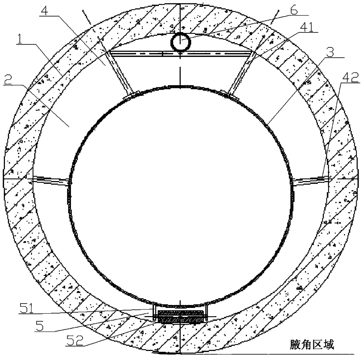
[0039] as attached figure 1 As shown, a casing-type water delivery pipeline for crossing bridges includes DN2400 concrete casing 1, concrete pouring layer 2 and pressure steel pipe 3. 1 set is arranged on the outside of the concrete pouring layer 2, and a supporting device 4 is connected between the DN2400 concrete casing 1 and the pressure steel pipe 3, and a steel roller 5 is fixed at the bottom of the pressure steel pipe 3.

[0040] The steel roller 5 includes a steel frame 51 welded to the bottom end of the penstock 3 and a rotatable steel roller 52 fixed on the steel frame 51 .

[0041] The supporting device 4 includes a steel support frame 41 welded on the top of the pressure steel pipe 3 and a steel support rod 42 welded on the side end of the pressure steel pipe 3, wherein both the steel support frame 41 and the steel support rod 42 abut against the inner wall of the DN2400 concrete casing 1 , There is also a space for placing the steel wire hose 6 between the steel s...

Embodiment 2

[0064] Step 2 also includes the steps of inserting steel rods in the reserved grouting holes in the outer middle section of the casing as external tension points, and linking 3t electric hoists to form an external tension system between the installed pipeline and the pipeline to be installed. In this embodiment, only the steps of inserting a steel rod as an external tension point and linking the 3t electric hoist are limited, and everything else is the same as in Embodiment 1.

Embodiment 3

[0066] Step 3 also includes the step of filling and compacting the axillary corner area of ​​the DN2400 concrete casing 1 with crushed stones, wherein a vibrating machine is used for compacting. In this embodiment, only the steps of filling and compacting are limited, and everything else is the same as in Embodiment 1.


PUM


Abstract

The invention discloses a casing pipe type water conveying pipeline applied to a crossing bridge and an installation and construction method thereof. The construction method comprises the following steps of: step 1. excavating a water conveying pipeline trench; step 2. installing a concrete casing pipe; step 3. backfilling the water conveying pipeline trench; step 4. installing a pressure steel pipe; step 5. filling concrete. A casing pipe type water conveying pipeline comprises the concrete casing pipe, a concrete pouring layer and the pressure steel pipe, wherein the concrete pouring layer is arranged at the outer side of the pressure steel pipe in a sleeving manner; the concrete casing pipe is arranged at the outer side of the concrete pouring layer in a sleeving manner; a supporting device is also connected between the concrete casing pipe and the pressure steel pipe; and steel idler wheels are also fixedly at the bottom of the pressure steel pipe. The construction method has closeworking procedure connection and effectively improves the construction efficiency. The stability of the pressure steel pipe is effectively ensured through the matching of the casing pipe layer structure and the supporting device, so that water is unlikely to seep from the pressure steel pipe.

Description


Claims


Application Information

Patent Timeline
Owner CHINA HYDROPOWER ELEVENTH ENG BUREAU ZHENGZHOU CO LTD
Why Eureka
Try Eureka