
Pit punching mechanism for lithium battery packaging equipment

A technology for packaging equipment and lithium batteries, used in non-aqueous electrolyte batteries, electrolyte battery manufacturing, sustainable manufacturing/processing, etc., can solve problems such as difficult operation, time-consuming disassembly and assembly, and achieve efficiency improvement, maintenance cost savings, positioning high precision effect

Pending Publication Date: 2019-02-12
东莞哈工自控科技有限公司
View PDF5 Cites 1 Cited by
  • Summary
  • Abstract
  • Description
  • Claims
  • Application Information

AI Technical Summary

Problems solved by technology

[0002] The upper and lower molds of the mold in the aluminum-plastic film punching mechanism of the traditional lithium battery packaging equipment adopt a split structure, which makes it difficult to operate when the mold is changed, and when the mold is fixed on the mold base, it is fastened with screws, which is time-consuming to disassemble.

Method used


Image

  • Pit punching mechanism for lithium battery packaging equipment
  • Pit punching mechanism for lithium battery packaging equipment
  • Pit punching mechanism for lithium battery packaging equipment

Examples


Embodiment Construction

[0027] The following describes the present invention in further detail with reference to the accompanying drawings and specific embodiments, without limiting the scope of implementation of the present invention.

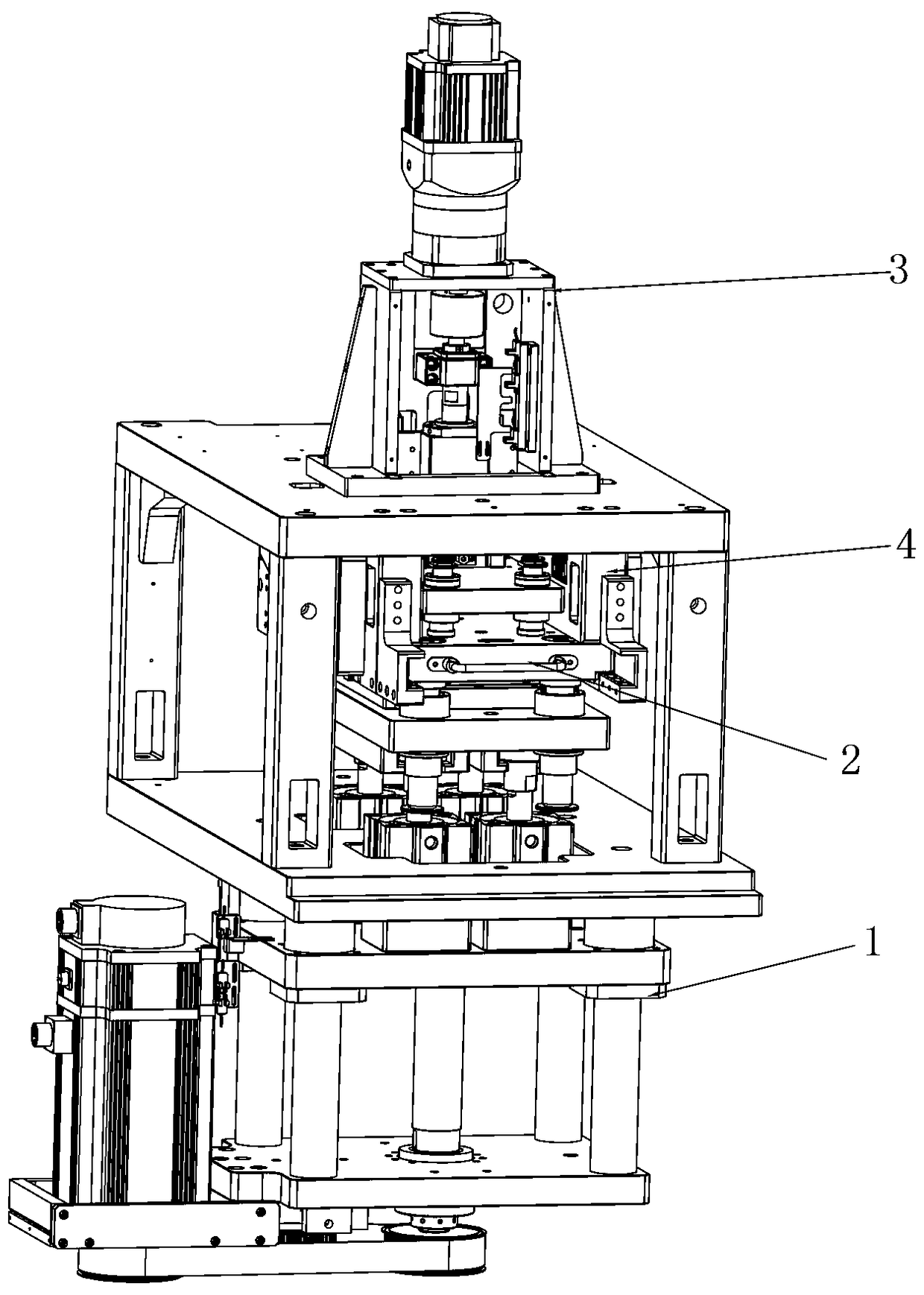
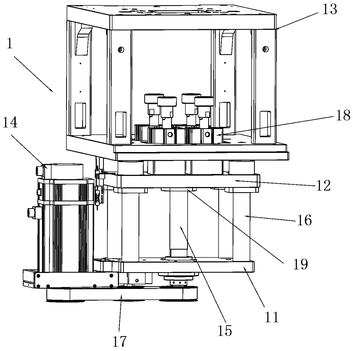
[0028] Such as Figure 1 to Figure 5 As shown, the punching mechanism of a lithium battery packaging device described in this embodiment includes a jacking device 1, a punching mold device 2, a punching drive device 3, and a punching mold fixing seat 4;

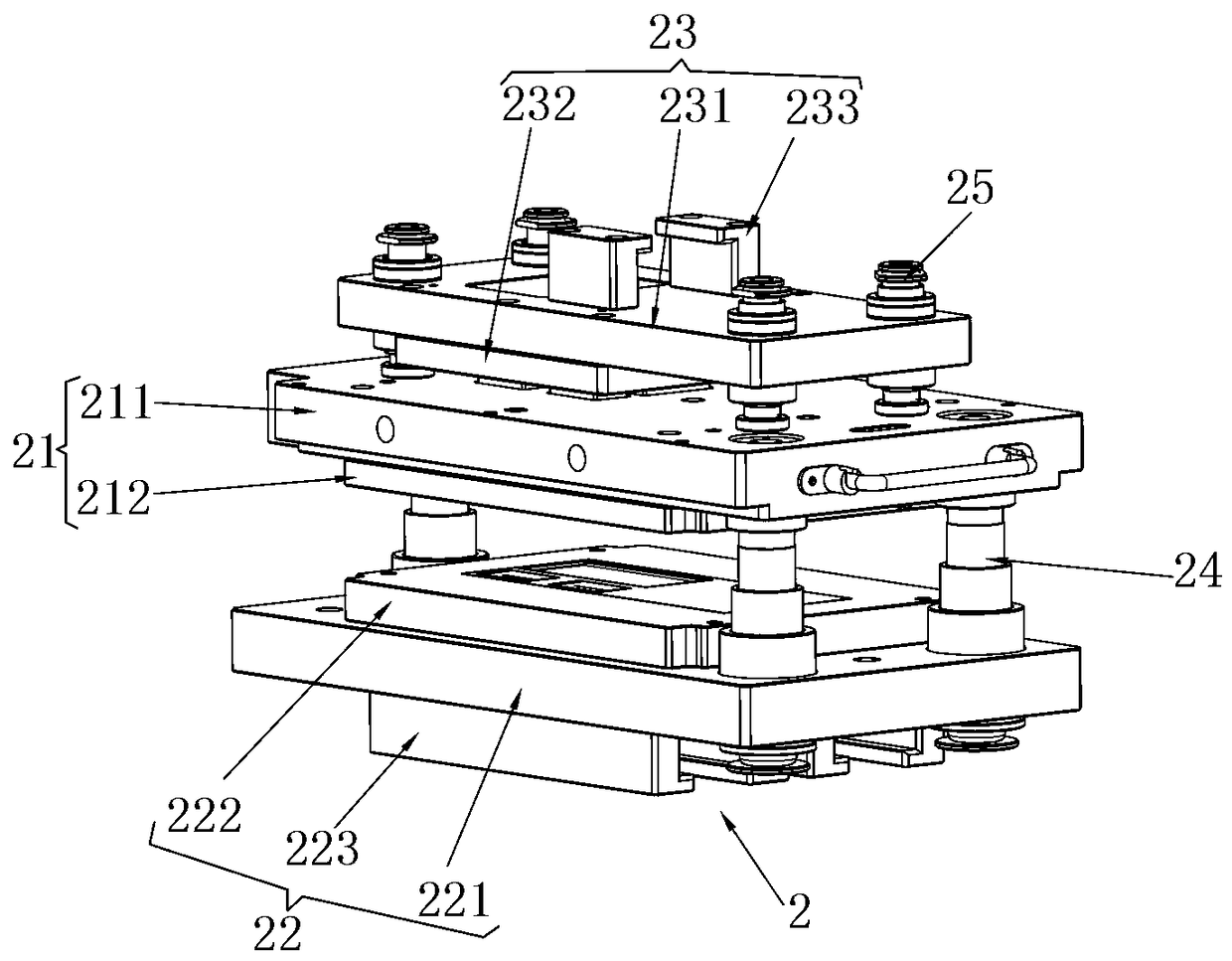
[0029] The punching mold device 2 includes an upper mold assembly 21, a lower mold assembly 22, and a punch assembly 23. The lower mold assembly 22 is fixed to the lower end of the upper mold assembly 21 through a first guide assembly 24, and the lower mold assembly 22 The lower end of the punch assembly 23 is connected to the jacking device 1, the punch assembly 23 is fixed to the upper end of the upper die assembly 21 through the second guide assembly 25, and the upper end of the punch assembly 23 is connected to the p...


PUM


Abstract

The invention discloses a pit punching mechanism for lithium battery packaging equipment. The pit punching mechanism comprises a jacking device, a pit punching mould device, a pit punching driving device and a pit punching mould fixing seat, wherein the pit punching mould device comprises an upper mould assembly, a lower mould assembly and a punching head assembly; the lower mould assembly is fixed to the lower end of the upper mould assembly through a first guiding assembly, the lower end of the lower mould assembly is connected with the jacking device, the punching head assembly is fixed tothe upper end of the upper mould assembly through a second guiding assembly, the upper end of the punching head assembly is connected with the pit punching driving device, and the upper mould assemblyis arranged on the pit punching mould fixing seat and can slide. According to the pit punching mechanism disclosed by the invention, when a mould is replaced, the mould can integrally slide to the pit punching mould fixing seat; thus, the whole pit punching mould device can be suspended and fixed on the pit punching mould fixing seat, quick mould replacement is achieved, the location accuracy ishigh, the mould replacement efficiency is greatly improved, and the maintenance cost is saved.

Description

Technical field [0001] The invention relates to the technical field of lithium battery packaging, in particular to a pit punching mechanism of a lithium battery packaging device. Background technique [0002] The upper and lower molds of the aluminum-plastic film punching mechanism of the traditional lithium battery packaging equipment adopt a split structure, which makes the mold change difficult to operate, and when the mold is fixed on the mold base, it is fastened by screws, which takes time to disassemble. Summary of the invention [0003] The purpose of the present invention is to overcome the above-mentioned shortcomings and provide a punching mechanism for lithium battery packaging equipment. [0004] In order to achieve the above objective, the specific scheme of the present invention is as follows: [0005] A punching mechanism for lithium battery packaging equipment, including a jacking device, a punching die device, a punching drive device and a punching die fixing seat; ...

Claims


Application Information

Patent Timeline
Patent Type & Authority Applications(China)
IPC IPC(8): H01M10/058
CPCH01M10/058Y02E60/10Y02P70/50
Inventor 钟遇舟邹同贵李昌奎
Owner 东莞哈工自控科技有限公司
Learn More