

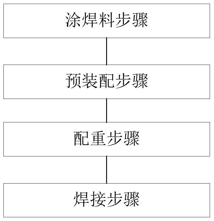
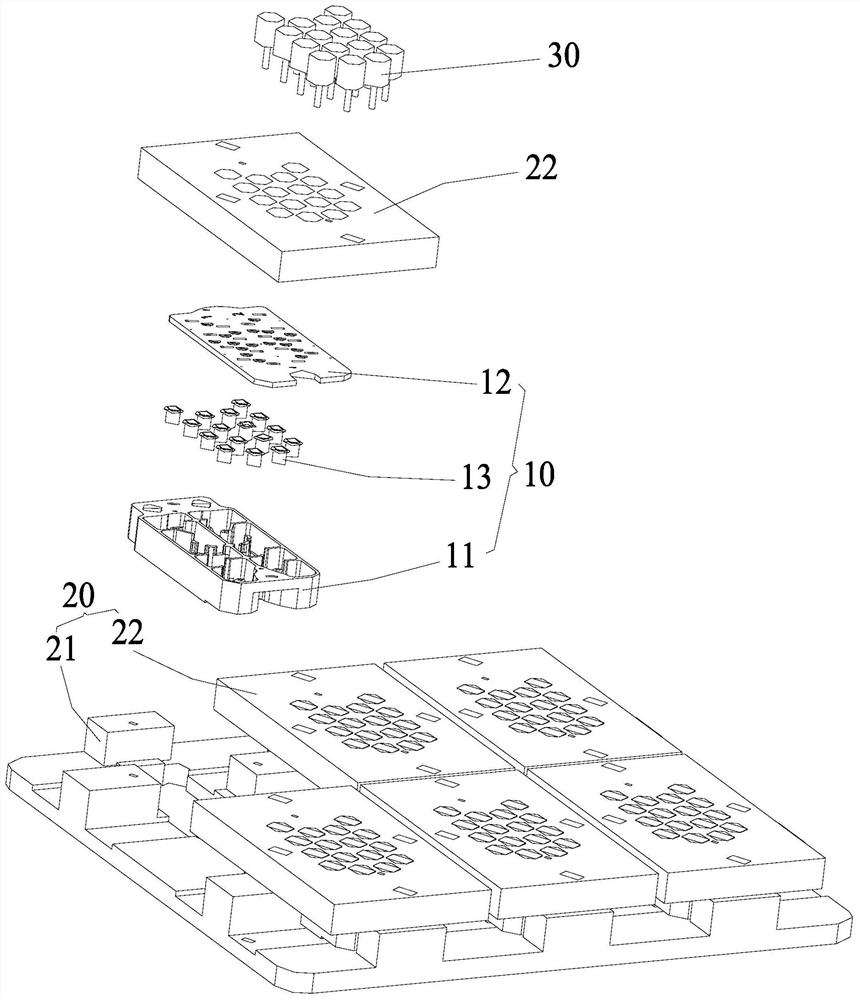
Cavity filter assembly process
A cavity filter and assembly process technology, which is applied to waveguide devices, circuits, electrical components, etc., can solve problems such as poor assembly efficiency, and achieve the effects of avoiding signal leakage, improving operating efficiency, and improving operating efficiency
- Summary
- Abstract
- Description
- Claims
- Application Information
AI Technical Summary
Problems solved by technology
Method used
Image

Examples
Embodiment Construction
[0027] In order to make the object, technical solution and advantages of the present invention clearer, the present invention will be further described in detail below in conjunction with the accompanying drawings and embodiments. It should be understood that the specific embodiments described here are only used to explain the present invention, not to limit the present invention.
[0028] It should be noted that when an element is referred to as being “fixed” or “disposed on” another element, it may be directly on the other element or be indirectly on the other element. When an element is referred to as being "connected to" another element, it can be directly connected to the other element or indirectly connected to the other element.
[0029] It should also be noted that the orientation terms such as left, right, up and down in the embodiments of the present invention are only relative concepts or refer to the normal use state of the product, and should not be regarded as re...
PUM
 Abstract
Description
Claims
Application Information