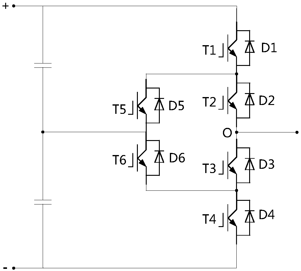
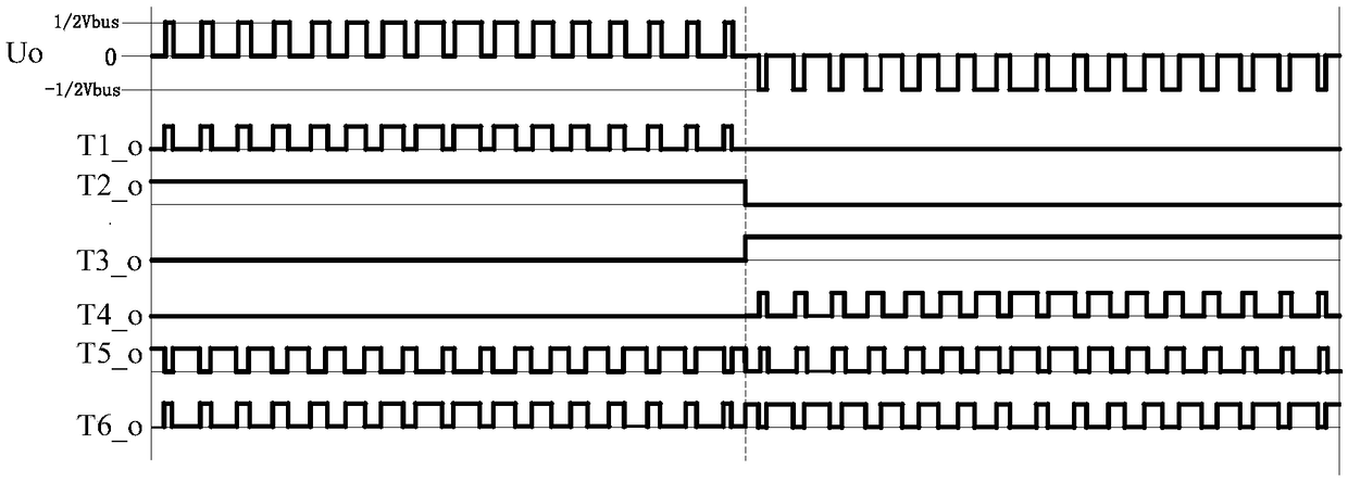
ANPC type three-level inverter and modulation method thereof
A technology of three-level inverter and modulation method, which is applied in the direction of electrical components, AC power input conversion to DC power output, output power conversion device, etc., and can solve problems such as overvoltage damage of switching tubes
- Summary
- Abstract
- Description
- Claims
- Application Information
AI Technical Summary
Problems solved by technology
Method used
Image
Examples
example 1
[0087] exist Figure 5a based on the obtained image 3 The enlarged waveform of the modulation method shown in the positive half cycle is shown in Fig. 7a, Figure 7a Among them, the starting time of deadtime1 is set to delay deadtime11, and the starting time of deadtime2 is set to remain unchanged. At this time, the driving waveforms of switching tubes T1, T5, and T6 are respectively shown in Figure 7a T1_dd, T5_dd, T6_dd in. exist Figure 5b On the basis of the obtained modulation method shown in Figure 4, the enlarged waveform of the positive half cycle is as follows Figure 7b as shown, Figure 7b In , the starting time of Deadtime3 is set to be delayed by deadtime33, and the starting time of deadtime4 is set to remain unchanged. At this time, the driving waveforms of switching tubes T4, T6, and T5 are respectively shown in Figure 7b T4_dd, T6_dd, T5_dd in.
[0088] That is, Figure 7a Compared to Figure 4a All the improvements are as follows: during the process...
example 2
[0090] exist Figure 5a based on the obtained image 3 The enlarged waveform of the modulation method shown in the positive half cycle is shown in Fig. 8a, Figure 8a, the starting time of deadtime1 and deadtime2 is set to remain unchanged, at this time, the driving waveforms of switching tubes T1, T5, T6 refer to Figure 8a T1_dd, T5_dd, T6_dd in. On the basis of Figure 5b, the enlarged waveform of the modulation method shown in Figure 4 in the positive half cycle is shown as Figure 8b as shown, Figure 8b In , the starting time of Deadtime3 and deadtime4 is set to remain unchanged, at this time, the driving waveforms of switching tubes T4, T6, T5 are respectively referred to Figure 7b T4_dd, T6_dd, T5_dd in.
[0091] That is to say, Figure 8a Compared to Figure 4a All the improvements are as follows: during the process of switching from 0 level to 1 / 2Vbus level, T1 delays the opening of deadtime1 time, T5 turns off on time, and T6 turns on in advance of deadtime11...
PUM
 Abstract
Description
Claims
Application Information
 - R&D
- Intellectual Property
- Life Sciences
- Materials
- Tech Scout
- Unparalleled Data Quality
- Higher Quality Content
- 60% Fewer Hallucinations
Browse by: Latest US Patents, China's latest patents, Technical Efficacy Thesaurus, Application Domain, Technology Topic, Popular Technical Reports.
© 2025 PatSnap. All rights reserved.Legal|Privacy policy|Modern Slavery Act Transparency Statement|Sitemap|About US| Contact US: help@patsnap.com


