
Preheating apparatus for limestone in lime production

A preheating device and limestone technology, applied in the field of limestone preheating device, can solve the problems of labor-intensive, no free movement, complicated cleaning actions, etc., and achieve the effect of reducing labor intensity, weakening compressive strength, and reducing manual handling.

Inactive Publication Date: 2018-12-11
朱治杰
View PDF0 Cites 1 Cited by
  • Summary
  • Abstract
  • Description
  • Claims
  • Application Information

AI Technical Summary

Problems solved by technology

[0004] The purpose of the present invention is to provide a limestone preheating device in lime production, to solve the problem that the existing lime production preheating device proposed in the background technology does not have the function of free movement, and the existing preheating device is closed as a whole Type structure, when the internal pollution of the preheating device is too much and deep cleaning is required, more complicated cleaning actions are required, thus causing the problem of labor-intensive

Method used

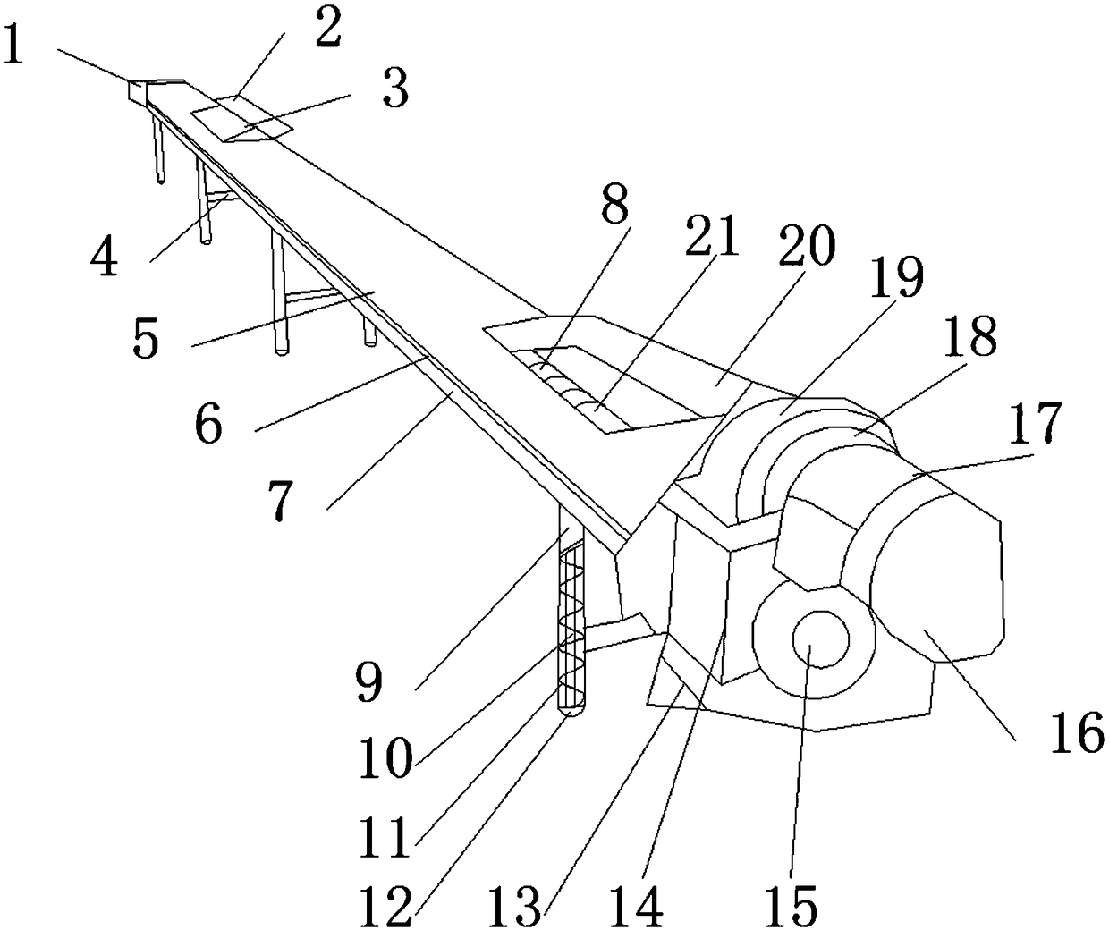
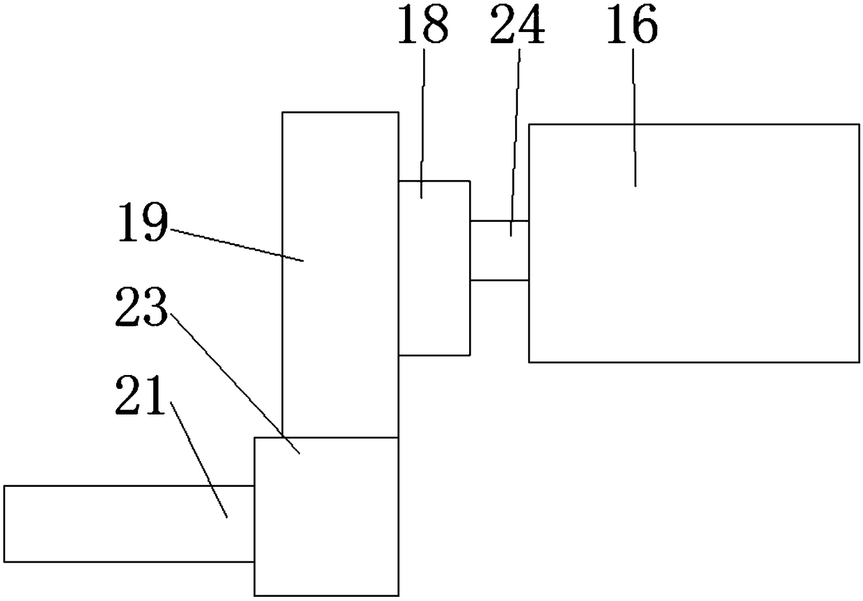

Image

  • Preheating apparatus for limestone in lime production
  • Preheating apparatus for limestone in lime production
  • Preheating apparatus for limestone in lime production

Examples


Embodiment 1

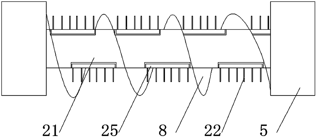
[0021] see Figure 1-3 , the present embodiment provides a limestone preheating device in lime production, including a feeding port 1, a cover plate 2, an observation hole 3, a cross rod 4, a top cover 5, a chute 6, a base 7, and a feeding chute 8. Support column 9, limit pole 10, shockproof spring 11, roller 12, mounting table 13, reducer housing 14, fixing piece 15, motor 16, motor anti-collision shell 17, first bevel gear 18, second Bevel gear 19, feed inlet 20, screw rod 21, heat conduction gear 22, coupling 23, motor output shaft 24 and heater 25, the bottom of base 7 is fixedly installed with support column 9, and the bottom of support column 9 is embedded and installed There are rollers 12, the rollers 12 are provided with a number that matches the support columns 9, and the top of the rollers 12 is equipped with a limit platform, and the inside of the limit platform is equipped with a limit buckle, and the middle of the two support columns 9 is provided with a horizont...

Embodiment 2

[0024] see Figure 1-3 , on the basis of Embodiment 1, a further improvement has been made: no less than six heat conduction teeth 22 are provided, and the fineness of stirring is improved, and the heat conduction teeth 22 are a member of an alloy steel material, which has good thermal conductivity, and at the same time avoids the heat conduction teeth 22 Due to the high hardness of limestone, it is very easy to cause damage to the heat conduction teeth 22. The groove wall of the feeding trough 8 is used in conjunction with the top cover 5 and the base 7, and the gap is small. It is only used to complete the rotation task and prevent incoming materials. drop problem.

[0025] Wherein, the heater 25 is embedded and installed in the inside of the installation block, and the installation is tight. The side of the installation block in contact with the heater 25 is provided with a heat insulation layer for heat insulation protection, preventing internal heat from escaping and caus...


PUM


Abstract

The invention discloses a preheating apparatus for limestone in lime production. The preheating apparatus comprises a feeding opening, a cover plate, an observation hole, a transverse supporting rod,a top cover, a sliding groove, a foundation support, a conveying groove, a supporting column, a limiting supporting rod, a shock-absorption spring, a roller, an installation table, a speed reducer shell, a fastener, a motor, a motor anti-collision shell, a first bevel gear, a second bevel gear, a material inlet, a screw rod, a heat conducting tooth, a connecting member, a motor output shaft and aheater, wherein the bottom of the foundation support is fixedly provided with the supporting column, the bottom of each supporting column is provided with the roller in an embedding manner, the middleparts of the two supporting columns are provide with the transverse supporting rod, and the top of the sliding groove is provided with the top cover in a sliding manner. By adopting the preheating apparatus, the problems that the existing lime production preheating apparatus does not have the freely moving function, the existing preheating apparatus is of an integrated closed structure, when a great amount of pollutants exist inside the preheating apparatus and the preheating apparatus needs to be further cleaned, the complicated cleaning work is needed, and the manpower is wasted can be solved.

Description

technical field [0001] The invention relates to the technical field of production devices, in particular to a limestone preheating device in lime production. Background technique [0002] What we usually call the effective content of lime refers to the content of calcium oxide (CAO) and magnesium oxide (MGO) contained in lime. These two substances play a decisive role in the strength of limestone base, especially After the hydration reaction with fly ash, the influence of its content is more significant. Increasing the lime dosage to a certain limit can naturally improve the strength of fly ash macadam, but this not only increases the construction cost, but also has a negative effect on improving the secondary The crack resistance of the gray gravel base is also very unfavorable. Therefore, lime with high effective content should be selected as much as possible. Usually, the lime must meet the standard of grade two ash, that is, the content of effective calcium and magnesium...

Claims


Application Information

Patent Timeline
Patent Type & Authority Applications(China)
IPC IPC(8): C04B2/10
CPCC04B2/10
Inventor 朱治杰
Owner 朱治杰
Learn More