Eureka AIR delivers breakthrough ideas for toughest innovation challenges, trusted by R&D personnel around the world.

Integration optimization connecting structure for furniture drawer and sliding rail

A technology for connecting structures and drawers, which is applied to drawers, furniture parts, household appliances, etc., can solve the problems of not meeting user requirements, affecting the fineness of drawers, and unstable assembly relationships, so as to improve the user experience, and the appearance is neat and beautiful. , the effect of simple and reasonable structure

Pending Publication Date: 2019-02-15
GUANGDONG DTC HARDWARE PRECISION MFG CO LTD
View PDF1 Cites 0 Cited by
  • Summary
  • Abstract
  • Description
  • Claims
  • Application Information

AI Technical Summary

Problems solved by technology

It is said that the structure is detachably connected between the side plate and the moving slide rail through a detachable locking mechanism, which makes the disassembly and assembly of the two quick and convenient; however, the gap formed inside the drawer of this structure after assembly More, affecting the fineness of the drawer, and the assembly relationship between the components is unstable, it is easy to cause damage due to human reasons during use, transportation or packaging, which affects the service life and leads to waste of materials, thereby increasing manufacturing costs , neither can meet the requirements of users, nor can manufacturers and sellers get higher profits from it.

Method used


Image

  • Integration optimization connecting structure for furniture drawer and sliding rail
  • Integration optimization connecting structure for furniture drawer and sliding rail
  • Integration optimization connecting structure for furniture drawer and sliding rail

Examples


Embodiment Construction

[0031] The present invention will be further described below with reference to the drawings and embodiments.

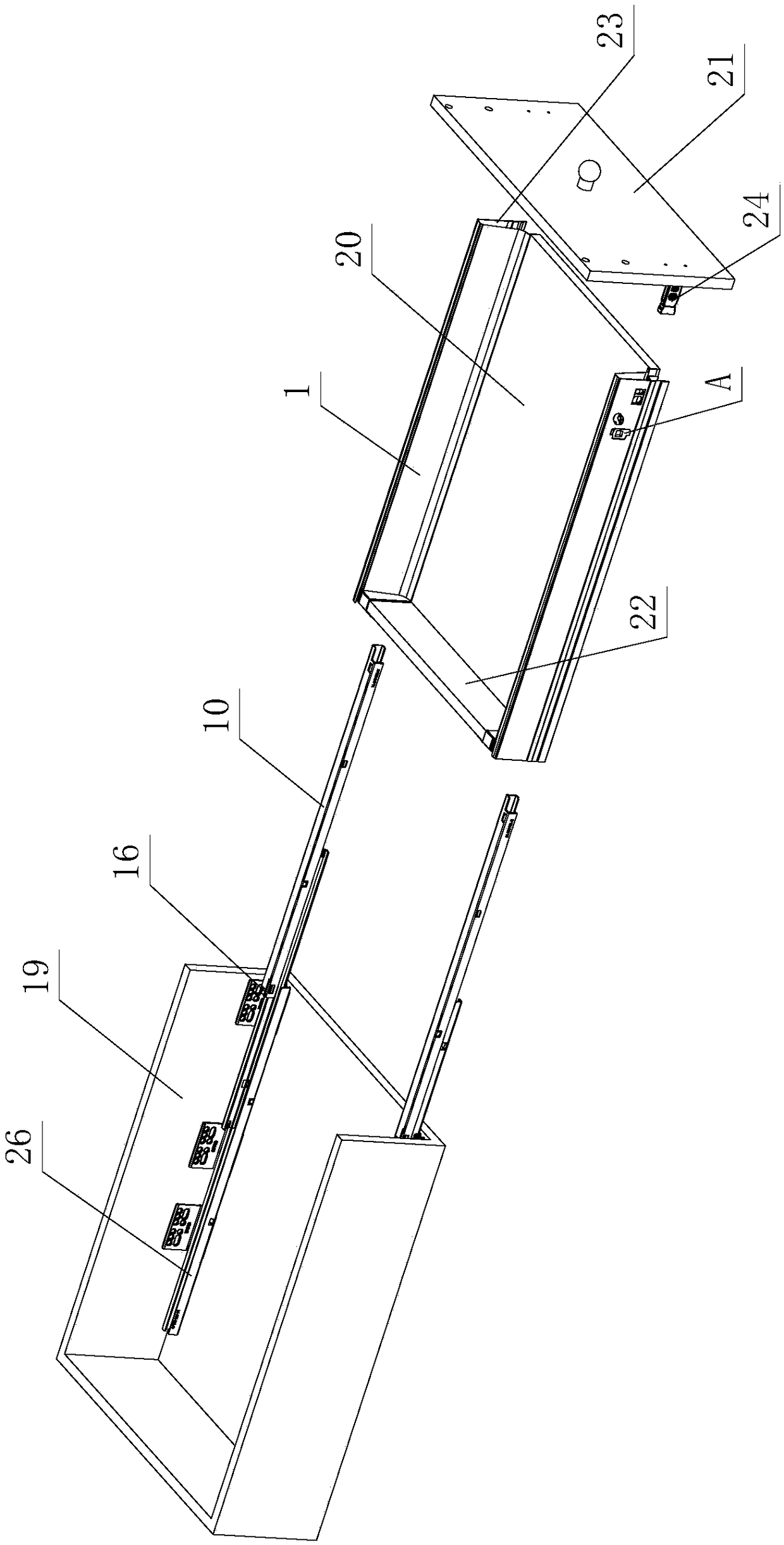
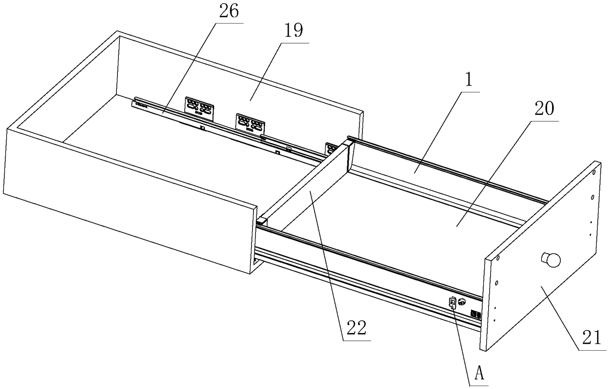
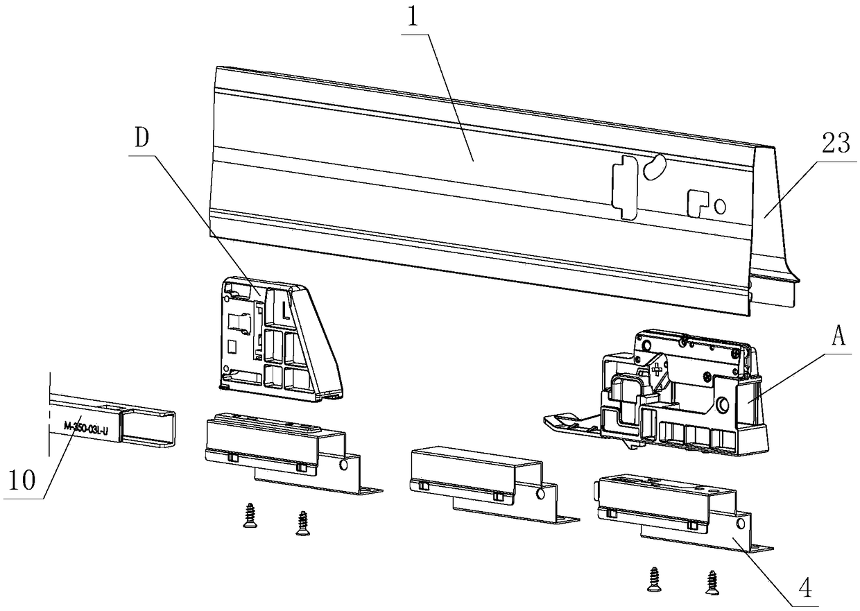
[0032] See Figure 1-Figure 13 , The integrated optimized connection structure used for furniture drawers and slide rails includes furniture drawers and slide rail assemblies. The furniture drawers at least include side panels 1, on which side panels 1 are provided with a locking and separating device A, which at least includes a bracket element 2. The bracket element 2 is provided with a fastening member 3 and a supporting member 4. The fastening member 3 is elastically movable on the supporting member 2. The supporting member 4 is made of metal material, and is provided with left and right limiting grooves 5 and supporting The step part 6, the support element 2 is provided with a soft plastic part 7, the upper and lower limit grooves 8 are formed between the support step part 6 and the support element 2, and the front and rear limit grooves are formed between the soft ...


PUM


Abstract

The invention discloses an integration optimization connecting structure for a furniture drawer and a sliding rail. The structure comprises the furniture drawer and a sliding rail assembly. The furniture drawer at least comprises side plates. The side plates are provided with locking and separating devices, each locking and separating device at least comprises a support component, a fastener and asupporting piece are arranged on each support component, each fastener is elastically and movably arranged on the corresponding support component, the supporting pieces are made of metal materials and provided with left-right limiting groove parts and bearing step parts, a soft plastic part is arranged on each support component, a vertical limiting groove part is formed between each bearing steppart and the corresponding support component, and a front-back limiting groove part is formed between each soft plastic part and the corresponding fastener; the sliding rail assembly at least comprises a movable sliding rail; the support component and the movable sliding rail are detachably buckled or separated through the fastener and the movable sliding rail and are in left-right, up-down and front-back limiting fit with the movable sliding rail through the left-right limiting groove parts, the vertical limiting grooves and the front-back limiting groove parts to achieve stable connection between the side plates and the sliding rail assembly. Due to the structure improvement, practicability is high.

Description

Technical field [0001] The invention relates to an integrated and optimized connection structure for furniture drawers and sliding rails. Background technique [0002] Chinese Patent Document No. CN203137617U on August 21, 2013 discloses a detachable locking mechanism for drawer slide rails and side panels. It includes side panels, a bottom plate, and a slide rail assembly for opening and closing the drawer. A front connector connected to the front panel and a rear connector connected to the back panel are provided. The side panel is provided with a slot for accommodating the bottom plate. The bottom plate is arranged on the slot and acts on the moving slide rail of the slide rail assembly A detachable locking mechanism is provided between the side plate and the movable slide rail, and the movable slide rail is detachably connected with the side plate through the locking mechanism. It is said that the structure is detachably connected between the side plate and the movable slide...

Claims


Application Information

Patent Timeline
Patent Type & Authority Applications(China)
IPC IPC(8): A47B88/427A47B88/49
CPCA47B88/427A47B88/49
Inventor 伍志勇
Owner GUANGDONG DTC HARDWARE PRECISION MFG CO LTD
Why Eureka
Eureka Blog
Learn More