
Laparoscope retractor

A laparoscopic and hook head technology, applied in the field of laparoscopic retractors, can solve the problems of inability to change the area of ​​the push-pull plane, unsuitable for various treatment scenarios, unable to meet medical needs, etc., achieving better cosmetic effects, saving operation time, and deformation. reduced effect

Pending Publication Date: 2019-02-15
ZHEJIANG UNIV
View PDF6 Cites 5 Cited by
  • Summary
  • Abstract
  • Description
  • Claims
  • Application Information

AI Technical Summary

Problems solved by technology

[0004] However, in minimally invasive laparoscopic surgery, especially some operations with small operating space, such as laparoscopic thyroid surgery, the surgical opening is a small hole. From the surgical opening into the abdominal cavity, it is necessary to first extend the H segment of the laparoscopic retractor into the surgical opening, then twist the laparoscopic retractor so that the G segment can be inserted into the surgical opening, and then twist the laparoscopic retractor so that the F segment can Extending into the surgical opening, the operation is not only complicated, but when the laparoscopic retractor is twisted, the HGF segment is likely to expand the skin wound and touch other tissues and organs, such as damage to important blood vessels, which may cause massive bleeding
[0005] Moreover, the area of ​​the push-pull plane of the traditional laparoscopic retractor cannot be changed, which is not suitable for a variety of treatment scenarios and cannot meet the current medical needs.

Method used


Image

  • Laparoscope retractor
  • Laparoscope retractor
  • Laparoscope retractor

Examples


Embodiment Construction

[0046] The present invention will be further described below in conjunction with the accompanying drawings.

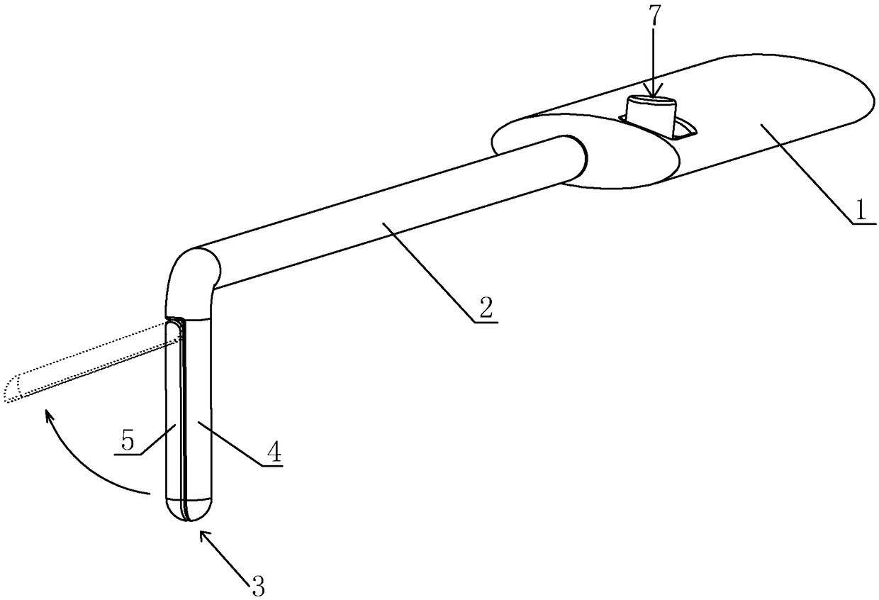
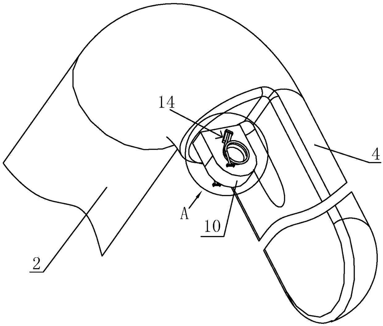
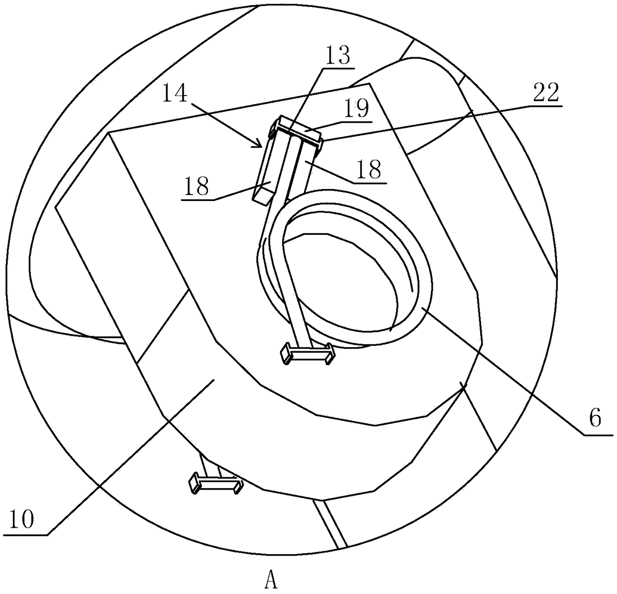
[0047] A laparoscopic retractor, such as Figure 1 to Figure 10As shown, it includes a handle 1, a connecting rod 2 and a hook head 3, the connecting rod 2 is fixedly connected between the handle 1 and the hook head 3, the hook head 3 includes a fixed rod 4 and a rotating rod 5, the upper end of the fixed rod 4 is connected to The rod 2 is fixedly connected, and the fixed rod 4 is fixedly connected with the connecting rod 2 at 90°; one end of the rotating rod 5 can be turned around the upper side of the fixed rod 4, and the maximum angle of the rotating rod 5 at the upper end of the fixed rod 4 is 80° ~90°; there is a torsion spring 6 between the connection between the fixed rod 4 and the rotating rod 5, and the rotating rod 5 forms a push-pull plane with the fixed rod 4 after being turned over by the elastic force of the torsion spring 6; The rod 2 and the handle 1 a...


PUM


Abstract

The invention discloses a laparoscope retractor. The laparoscope retractor comprises a gripping handle, a connecting rod and a retractor head; the connecting rod is fixedly connected between the gripping handle and the retractor head, the retractor head comprises a fixed rod and a rotary rod, the upper end of the fixed rod is fixedly connected with the connecting rod, and one end of the rotary rodcan relatively turn over around one side of the upper end of the fixed rod; torsion springs are arranged between the fixed rod and the rotary rod, and the rotary rod turns over under the elastic force of the torsion springs to form a push-pull plane with the fixed rod; the gripping handle is provided with a control switch, a through inner cavity is formed in the connecting rod and the gripping handle and internally provided with a pulling wire, one end of the pulling wire is connected with the rotary rod, the other end of the pulling wire is connected with the control switch, and the controlswitch is drives the rotary rod to relatively turn over at the upper end of the fixed rod through the pulling wire. According to the laparoscope retractor, the fixed rod is provided with the rotary rod capable of relatively turning over, the rotary rod can rotate to be parallel to the fixed rod, the retractor conveniently extends into operation space from a minimally invasive surgical incision accordingly, and when the retractor extends into the operation space, the rotary rod turns over on the fixed rod under the elastic force of the torsion springs to form the push-pull plane.

Description

technical field [0001] The invention relates to the field of medical instruments, in particular to a laparoscopic retractor. Background technique [0002] In the minimally invasive laparoscopic medical surgery in the human body, the tissues and organs in the abdominal cavity need to be pushed or pulled by the laparoscopic retractor to move to a suitable position before surgical operation can be performed. [0003] Traditional laparoscopic retractor as attached Figure 11 As shown, in order to make the laparoscopic retractor form a push-pull plane that can be used to push or pull the tissues and organs in the abdominal cavity, the E segment and the H segment are set as corresponding curved segments, so that the F segment, the G segment and the H segment are connected to form a push-pull plane, The push-pull plane of the laparoscopic retractor is conducive to freeing up a larger treatment space when pushing or pulling tissues and organs, so as to facilitate surgical operation ...

Claims


Application Information

Patent Timeline
IPC IPC(8): A61B17/02
CPCA61B17/0218A61B17/0281
Inventor 叶茂
Owner ZHEJIANG UNIV
Learn More