Longitudinal mechanical flexibility compensation device for worktable of bending machine and manufacturing method of longitudinal mechanical flexibility compensation device

A compensation device and worktable technology, applied in the field of bending machines, can solve problems such as accumulated errors and inconsistencies in compensation values, and achieve the effects of enhancing wear resistance, high movement consistency, and ensuring accuracy

Pending Publication Date: 2019-02-15
ANHUI LIYUAN NUMERICAL CONTROL CUTTING TOOL & PATTERNS MFG
View PDF3 Cites 12 Cited by
  • Summary
  • Abstract
  • Description
  • Claims
  • Application Information

AI Technical Summary

Problems solved by technology

[0005] Aiming at the clearance fit between the upward inclined block and the upper fixed plate and the downward inclined block and the lower carriage in the prior art, there is a cumulative error, which leads to the problem that the compensation value of the downward inclined block group is inconsistent when it moves left an

Method used


Image

  • Longitudinal mechanical flexibility compensation device for worktable of bending machine and manufacturing method of longitudinal mechanical flexibility compensation device
  • Longitudinal mechanical flexibility compensation device for worktable of bending machine and manufacturing method of longitudinal mechanical flexibility compensation device
  • Longitudinal mechanical flexibility compensation device for worktable of bending machine and manufacturing method of longitudinal mechanical flexibility compensation device

Examples


Example Embodiment

[0042] Example 1

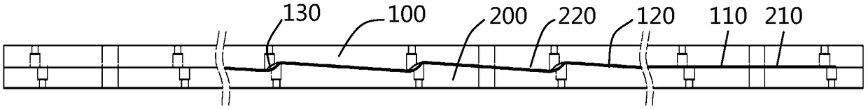
[0043] Such as figure 1 Shown is a structural schematic diagram of a longitudinal mechanical deflection compensation device for a workbench of a bending machine in the prior art, in which the lower inclined block includes a certain number. The defects of the compensation device are: (1) the upper inclined block and the upper fixed plate and the lower inclined block There is a clearance fit between the block and the lower carriage, and there is a cumulative error, which leads to inconsistent compensation values ​​when the lower inclined block group moves to the left and right (the production error caused by the tool wear); (2) the carriage uses laser Cutting and forming have length errors due to thermal expansion and contraction; the slope of the oblique block is formed by a grinder, and the production efficiency is low.

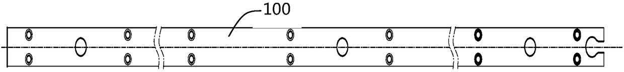
[0044] Please refer to Figure 2 to Figure 4 , The longitudinal mechanical deflection compensation device of the worktable of the bending mach...

Example Embodiment

[0050] Example 2

[0051] The working principle of this embodiment is: in the manufacturing process of the longitudinal mechanical deflection compensation device of the worktable, the wedge groups are evenly distributed along the rectangular groove 310, the angle of the middle wedge is the largest, and the angles decrease sequentially along the length. The lower end of the hydraulic cylinder The wedge angle is the smallest (usually 0.08°). When the wedge is offset equidistantly, because the middle wedge angle is large, the center of the worktable can be raised to form a corresponding deflection curve to achieve the purpose of deflection compensation.

[0052] The DEFORM finite element analysis software is used to simulate and analyze the springback of sheet metal. At the same time, the orthogonal test method is used to effectively deal with the influencing factors. The purpose of the orthogonal test is to observe the rebound angle by changing the level of each factor. Size, so as t...

Example Embodiment

[0057] Example 3

[0058] The manufacturing method of the longitudinal mechanical deflection compensation device of the worktable of the bending machine of this embodiment includes the steps:

[0059] S101. Select two plates of the same high-strength steel material, 60# carbon steel chemical composition: C content is 0.6%; Si content is 0.2%; Mn content is 0.6%; Cr content is ≤0.25%; Ni content is ≤0.30%; Cu Content≤0.25%, the rest is Fe;

[0060] S102. On the CNC machine tool, determine one end of the upper inclined plate 100 as the starting point of machining, and use the vertical surface to machine the first inclined surface 120 of the upper inclined plate 100, where the amount of cutting per time L1=[W(C) / W(Si )]*0.1=0.6 / 0.2*0.1=0.3mm; knife speed V1=[(W(C)+W(Mn)) / W(Si)]*500=(0.6+0.6) / 0.2*500= 3000mm / min, W(C), W(Mn), W(Si) all represent weight percentages. The slope K of the first inclined surface 120 determines the value of different segments according to the deflection curve...


PUM

PropertyMeasurementUnit
Thicknessaaaaaaaaaa

Abstract

The invention discloses a longitudinal mechanical flexibility compensation device for a worktable of a bending machine and a manufacturing method of the longitudinal mechanical flexibility compensation device, and belongs to the technical field of bending machines. The longitudinal mechanical flexibility compensation device comprises an upper sloping plate and a lower sloping plate; the upper sloping plate and the lower sloping plate are of an integral structure and consistent in size; first slope surfaces in the longitudinal direction are arranged on the lower surface of the upper sloping plate; the slopes of the first slope surfaces are reduced from a larger slope Kj to a smaller slope Ki from the middle to the two ends; the two adjacent first slope surfaces are connected through an arcsurface; the radians of the arc surfaces are increased from a smaller radian Ri to a larger radian Rj from the middle to the two ends; and second slope surfaces corresponding to the first slope surfaces are arranged on the upper surface of the lower sloping plate. The upper sloping plate and the lower sloping plate are of an integrated structure and consistent in size, so that the moving consistency of the lower sloping plate is high, accumulative errors can be eliminated or cancelled, and the bending molding accuracy is ensured.

Description

technical field [0001] The invention belongs to the technical field of bending machines, and more specifically relates to a longitudinal mechanical deflection compensation device of a working table of a bending machine and a manufacturing method thereof. Background technique [0002] In the process of bending the plate, the bending machine often inevitably has the elastic deformation of the slider caused by the force of its own structure. Although the deformation is extremely small, for high-precision bending workpieces, the workpiece is still It is prone to deflection and deformation, and the consistency of the angle cannot be guaranteed. For traditional bending machines that use hydraulic pressure as the force source, due to the uneven force applied by the oil cylinder, a deflection will be generated in the length direction of the workpiece during the bending process, and the ultra-long bending die is also often used for bending Bending shorter workpieces will cause the u...

Claims


Application Information

Patent Timeline
IPC IPC(8): B21D5/00B21D37/01B23Q23/00
CPCB21D5/00B21D37/01B23Q23/00
Inventor 张一帆胡有青张迎年张波
Owner ANHUI LIYUAN NUMERICAL CONTROL CUTTING TOOL & PATTERNS MFG
Why Eureka
Try Eureka