
Self-propelled multi-arm robot cleaning machine

A robotic and self-propelled technology, which is applied in the direction of abrasive jetting machine tools, used abrasive processing devices, abrasives, etc., can solve the problems of fixed-point shot blasting, inability to collide with structures, and inflexibility, etc., to achieve a wide range of cleaning operations, Meet environmental protection requirements, highly automated effect

Inactive Publication Date: 2019-02-15
青岛淳九机器控股有限公司
View PDF2 Cites 0 Cited by
  • Summary
  • Abstract
  • Description
  • Claims
  • Application Information

AI Technical Summary

Problems solved by technology

[0002] The existing robot cleaning equipment mainly refers to the manipulator shot blasting machine. The manipulator is mainly used for loading and unloading parts or clamping the workpiece into the shot blasting room for shot peening. For shot blasting, this method cannot be used for relatively large workpieces. For some large workpieces that are inconvenient to move, there are some mobile shot blasting equipment, but it is limited to some two-dimensional movement of the shot blasting equipment along the track. Bulky and not flexible enough to do some selective spot peening

Method used


Image

  • Self-propelled multi-arm robot cleaning machine
  • Self-propelled multi-arm robot cleaning machine

Examples


Embodiment 1

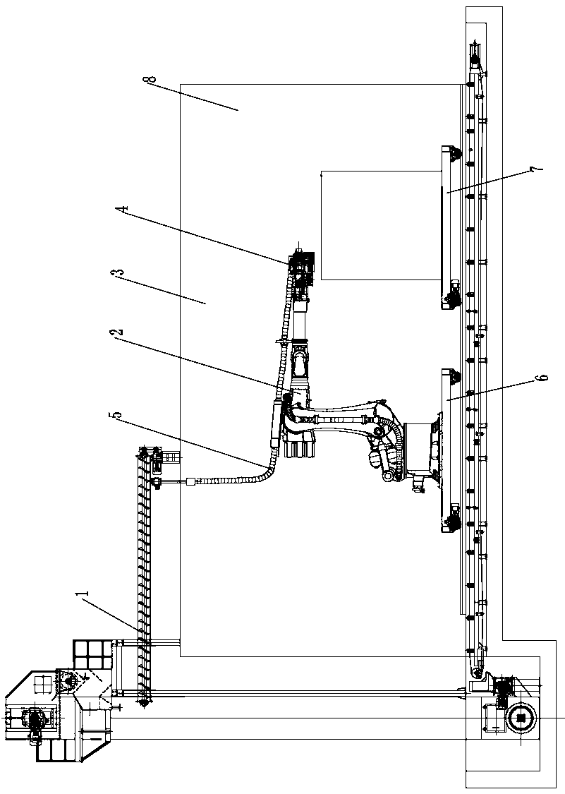
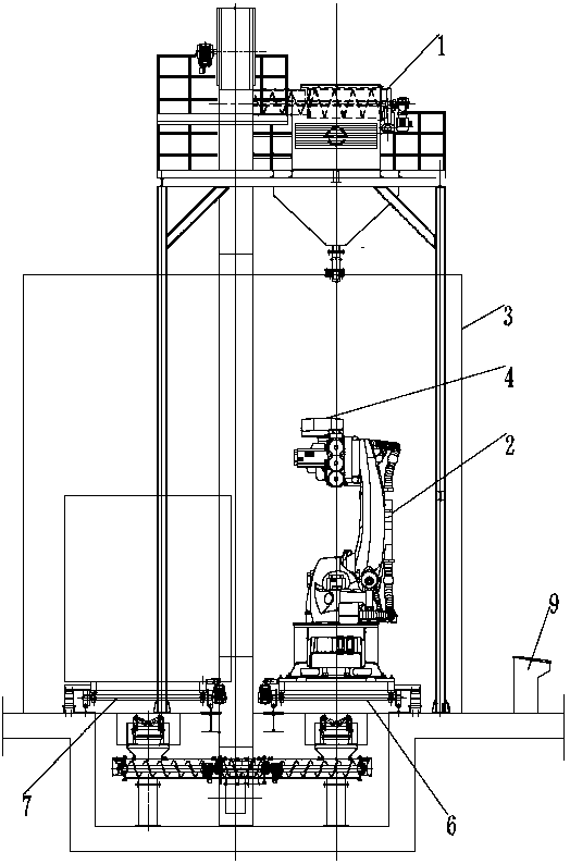
[0020] see Figure 1~2 , in an embodiment of the present invention, a self-propelled multi-arm robot cleaning machine includes a horizontally arranged support installation plate, a support installation column is vertically arranged on the left end of the support installation plate, and a vertical support installation column is arranged on the upper end of the support installation plate. There is a shot blasting chamber 3, and two sets of moving guide rails are horizontally arranged on the front and back of the support mounting plate in the shot blasting chamber 3, and a workpiece moving trolley 7 is horizontally arranged on the upper end of the moving guide rails at the front end, and a workpiece is installed on the upper end of the workpiece moving trolley 7. , and the lower end of the workpiece mobile trolley 7 is equipped with moving guide wheels before and after the moving guide rails, the upper end of the moving guide rails at the rear end is horizontally provided with a r...

Embodiment 2

[0022] On the basis of Embodiment 1, a dust removal system 8 is integrated at the upper right end of the shot blasting chamber 3, and the dust removal system 8 removes dust generated by shot blasting to meet environmental protection requirements.


PUM


Abstract

The invention relates to the field of automation equipment, in particular to a self-propelled multi-arm robot cleaning machine comprising a horizontally arranged support installing plate. A support installing column is vertically arranged at the left end of the support installing plate. A shot blasting chamber is vertically arranged at the upper end of the support installing plate. Two sets of moving guide rails are arranged horizontally front and back in the positions, in the shot blasting chamber, of the upper end of the support installing plate. A workpiece moving trolley is arranged at theupper end of the moving guide rail at the front end horizontally. A robot moving flatcar is horizontally arranged at the upper end of the moving guide rail at the rear end. According to bearing movement and rotation of the workpiece moving trolley and coherent operation of a shot blasting system, shot blasting cleaning work in the moving process is achieved, thus the cleaning work range is wide,the self-propelled multi-arm robot cleaning machine can adapt to deep-inner-cavity large workpiece cleaning work and has high automation and good adaptation, dust in cleaning work is removed, and environment protection requirements are met.

Description

technical field [0001] The invention relates to the field of automation equipment, in particular to a self-propelled multi-arm robot cleaning machine. Background technique [0002] The existing robot cleaning equipment mainly refers to the manipulator shot blasting machine. The manipulator is mainly used for loading and unloading parts or clamping the workpiece into the shot blasting room for shot peening. For shot blasting, this method cannot be used for relatively large workpieces. For some large workpieces that are inconvenient to move, there are some mobile shot blasting equipment, but it is limited to some two-dimensional movement of the shot blasting equipment along the track. Bulky and not flexible enough to do some selective spot peening. [0003] In order to solve the above problems, the present invention is proposed. According to the movement and rotation of the workpiece moving trolley and the coherent operation of the shot blasting system, the shot blasting clea...

Claims


Application Information

Patent Timeline
Patent Type & Authority Applications(China)
IPC IPC(8): B24C3/02B24C9/00
CPCB24C3/02B24C9/00B24C9/003
Inventor 郭合松宋德臣王文文
Owner 青岛淳九机器控股有限公司
Learn More