Multifunction domestic garbage can

A trash can, multi-functional technology, applied in the field of daily necessities, can solve the problems of single function, large amount of activated carbon, inconvenience, etc., and achieve the effect of prolonging the service life

Inactive Publication Date: 2019-02-15
肖华林
View PDF0 Cites 1 Cited by
  • Summary
  • Abstract
  • Description
  • Claims
  • Application Information

AI Technical Summary

Problems solved by technology

However, the inventors have found that the activated carbon adsorption method is limited due to the limited adsorption capacity of activated carbon, and the activated carbon bag needs to be replaced frequently, which is inconvenient and requires a large amount of activated carbon.
In addition, the existing trash can has a single function

Method used


Image

  • Multifunction domestic garbage can
  • Multifunction domestic garbage can
  • Multifunction domestic garbage can

Examples


Embodiment 1

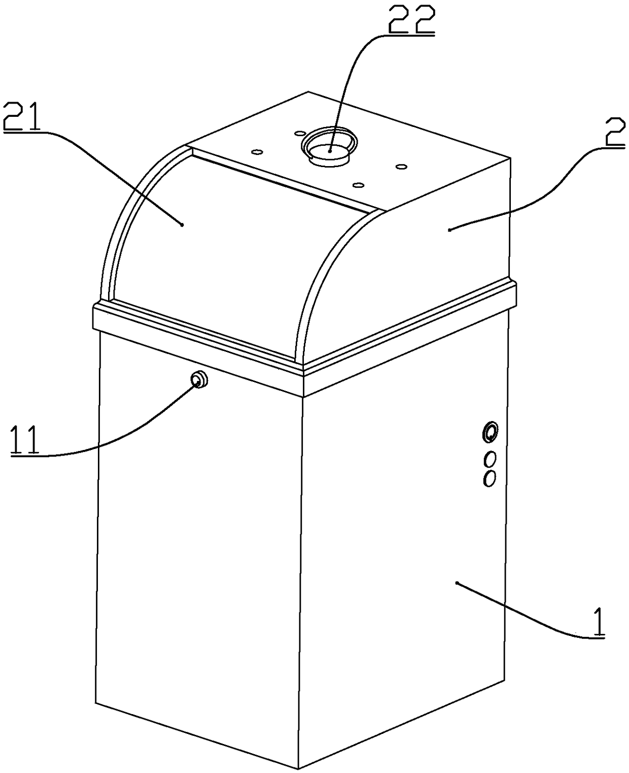
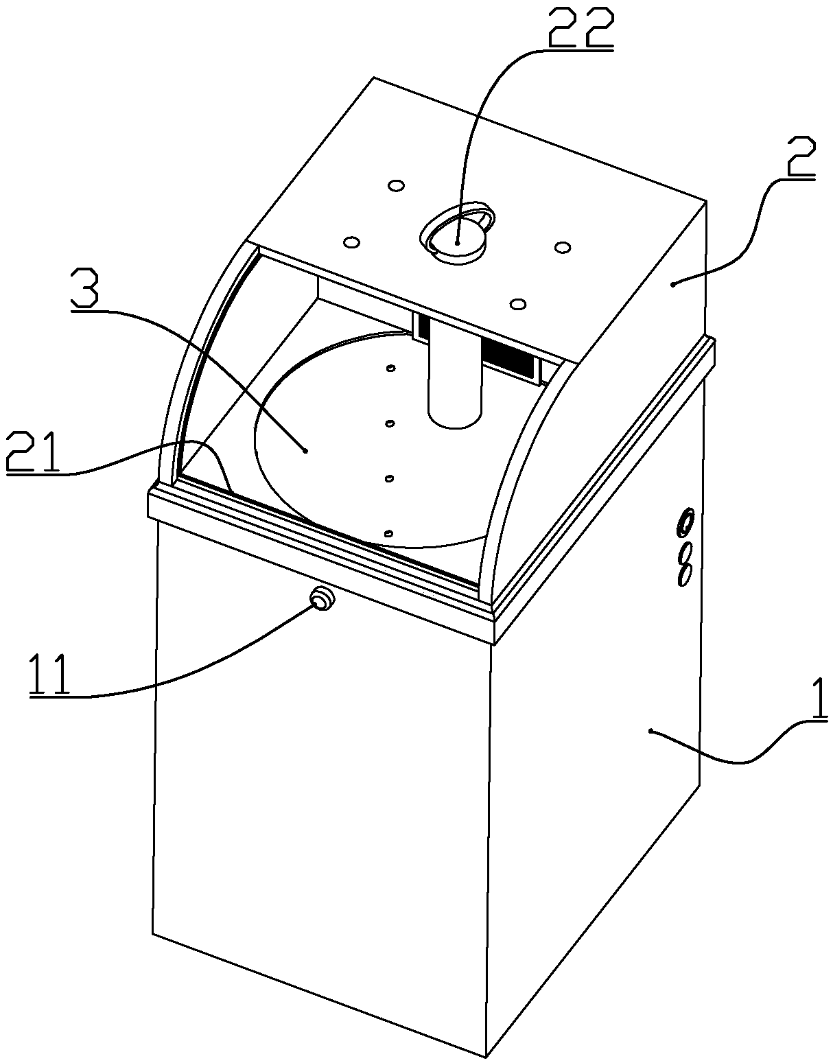
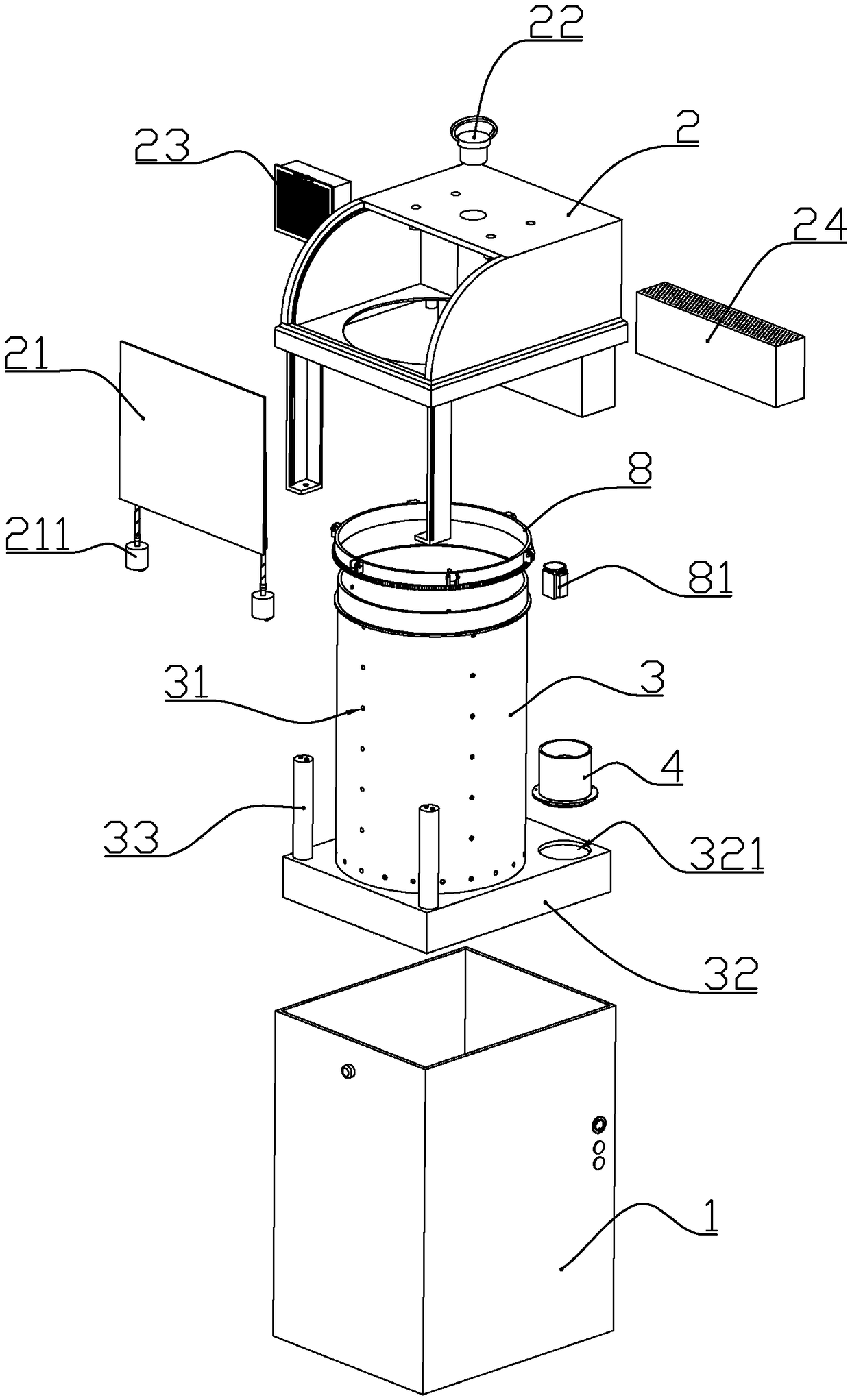
[0041] according to Figure 1 to Figure 8 As shown, the present embodiment is a multifunctional household waste bin, comprising a cuboid-shaped outer barrel 1 with an open upper end, a cylindrical inner barrel 3 installed in the outer barrel from top to bottom, and a detachably sleeved outer barrel The bung 2 at the upper end.

[0042] The lower end of the inner barrel is integrally connected with a lower support 32 that matches the shape of the inner circumference of the outer barrel. Two fans 4 that supply air from top to bottom are installed on the upper end of the rear side of the lower support. A fan installation port 321 is formed at the position where the fan is installed; an air exhaust port 12 is formed at the lower end of the rear wall of the outer barrel, and the lower part of the lower support is connected to the air exhaust port.

[0043] The front upper part of the lid is formed with an arc-shaped garbage throwing inlet, and the two sides of the garbage throwing...

Embodiment 2

[0055] combine Figure 1 to Figure 11 As shown, the present embodiment makes the following improvements on the basis of embodiment 1:

[0056] The inner top of the bung is positioned above the inner bucket to form a suction pipe 201 that penetrates up and down. The upper end of the suction pipe is sealed and inserted with a plug 22 , or connected to the suction head 5 through a hose 51 . The lower end of the suction pipe is connected with an inner extension pipe 2011, and the lower end of the inner extension pipe extends below the mouth of the inner barrel, so that the humidified dust is discharged into the inner barrel from the lower end of the inner extension pipe, and the dust that enters the dust filter flows upwards Significantly reduced, prolonging the service life of the dust filter.

[0057] The humidification assembly 7 includes a water tank 71 and a water tank cover 72 sealingly connected to the upper end of the water tank. A mist inlet pipe 711 is formed in the mid...

Embodiment 3

[0068] combine image 3 , Figure 12 In this embodiment, the following improvements are made on the basis of Embodiment 1 or 2: a support bead 35 is formed on the upper periphery of the inner barrel, and a rotating ring 8 is provided on the outer periphery of the inner barrel above the support bezel. The outer wall of the rotating ring 7 is formed with 5-8 sets of wheel bases 801, and each set of wheel bases is rotatably connected with a sticky wheel 802 made of thermoplastic material or soft silicone material through a pin shaft. The interference fit makes the viscous wheel need to overcome the frictional force when rotating relative to the pin shaft; the outer wall of the rotating ring is located under the wheel seat and formed with driven teeth 803, and the inner wall of the outer barrel is equipped with a sealing motor 81 that drives the rotating ring to rotate , the output shaft of the sealing motor is connected with a drive gear meshing with the driven gear.

[0069] T...


PUM


Abstract

The invention discloses a multifunction domestic garbage can. The multifunction domestic garbage can comprises an outer can, a cylindrical inner can mounted in the outer can, and a can cover arrangedat the upper end of the outer can in a sleeving mode; the lower end of the inner can is integrally connected with a lower support matched with the inner periphery of the outer can in shape, two fans are mounted at the upper end of the rear side of the lower support, and fan mounting openings are formed in the positions, provided with the fans, of the lower support; exhaust outlets are formed in the lower end of the rear wall surface of the outer can; an arc-shaped garbage throwing-in opening is formed in the upper-front part of the can cover, baffle guiding grooves are symmetrically formed inthe positions, on the two sides of the garbage throwing-in opening, of the can cover, and an elastic baffle used for blocking the garbage throwing-in opening is slidably mounted between the two baffleguiding grooves in the two sides; and a pyroelectric sensor used for detecting whether a user gets close to the domestic garbage can or not is mounted on the upper part of the front side of the outercan. When the pyroelectric sensor detects the situation that the user gets close to the domestic garbage can, the fans work, then the elastic baffle moves downwards to enable the garbage throwing-inopening to be opened, and in this way, undesirable odors of garbage are not smelt by the user in the process that the user throws the garbage.

Description

technical field [0001] The invention belongs to the field of daily necessities, and in particular relates to a household multifunctional trash can. Background technique [0002] In the existing garbage cans with deodorizing function, the general method is to place activated carbon bags in the garbage can to absorb the peculiar smell, or to spray bactericidal liquid in the garbage can to inhibit the reproduction of bacteria and reduce the peculiar smell. However, the inventors found that the activated carbon adsorption method requires frequent replacement of the activated carbon bag due to the limited adsorption capacity of the activated carbon, which is inconvenient and consumes a large amount of activated carbon. In addition, the existing trash can has a single function. Contents of the invention [0003] The technical problem to be solved by the present invention is: aiming at the deficiencies in the prior art, to provide a novel structural design, which can ensure that...

Claims


Application Information

Patent Timeline
Patent Type & Authority Applications(China)
IPC IPC(8): B65F1/14B65F1/10B65F1/08B65F1/06B65F1/16
CPCB65F1/06B65F1/08B65F1/105B65F1/14B65F1/1415B65F1/16B65F1/1607B65F7/00B65F2210/1026B65F2210/129B65F2210/137
Inventor 不公告发明人
Owner 肖华林
Why Eureka
Try Eureka