
Wire harness dyeing device and method

A dyeing device and wire harness technology, applied in the field of dyeing devices, can solve problems such as unsuitable installation of lamps, shortening of dyeing time, and difficulty in coloring, so as to achieve stable lighting light, ensure the quality of dyed threads, and ensure the lighting requirements.

Active Publication Date: 2021-03-12
永春县产品质量检验所福建省香产品质量检验中心国家燃香类产品质量监督检验中心福建
View PDF10 Cites 0 Cited by
  • Summary
  • Abstract
  • Description
  • Claims
  • Application Information

AI Technical Summary

Problems solved by technology

[0002] Usually, the wire harness is put into a dyeing pool filled with a dye solution for dyeing. At high temperature, the wire harness is easier to color and the dyeing time will be shortened. Therefore, the dye solution needs to be heated, and a large number of wire harnesses need to be processed at one time during the dyeing process. However, due to the volatilization of a large amount of steam, the water vapor above the dyeing pool is too heavy, which is not suitable for installing lamps. It is very difficult to observe the coloring of the wire harness in the dyeing pool. It is prone to uneven dyeing, and the undyed wire harness can only be treated at a reduced price, resulting in economic losses

Method used


Image

  • Wire harness dyeing device and method
  • Wire harness dyeing device and method
  • Wire harness dyeing device and method

Examples


Embodiment 1

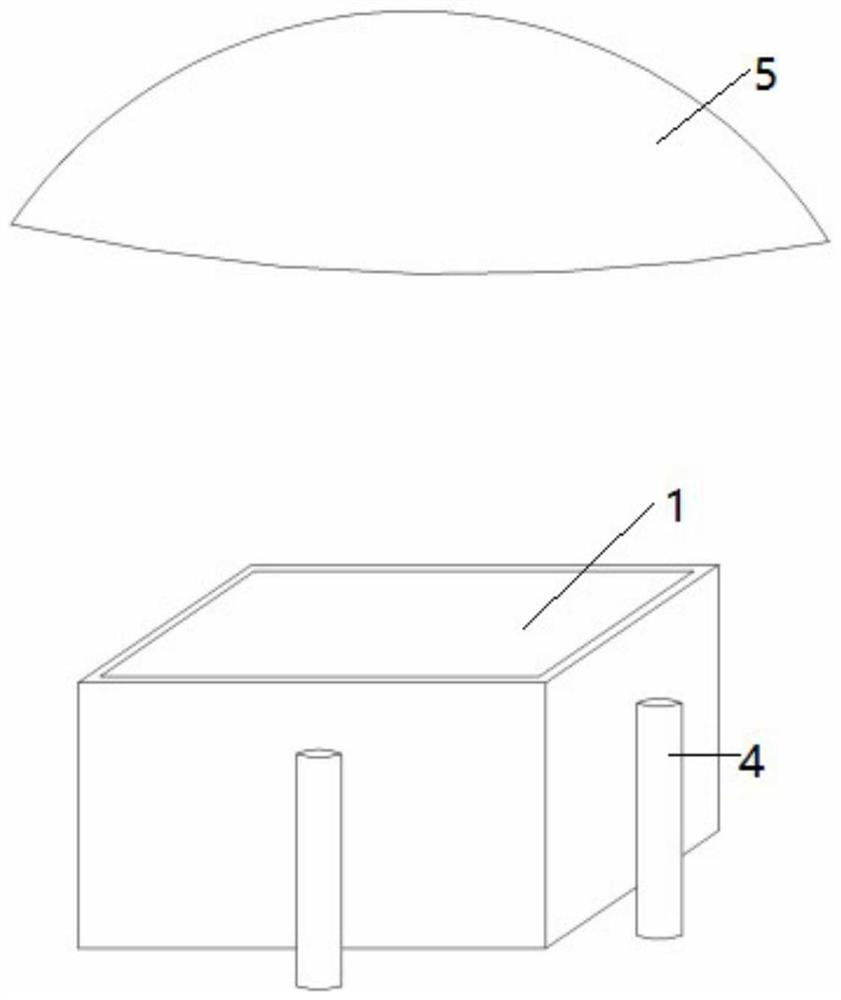
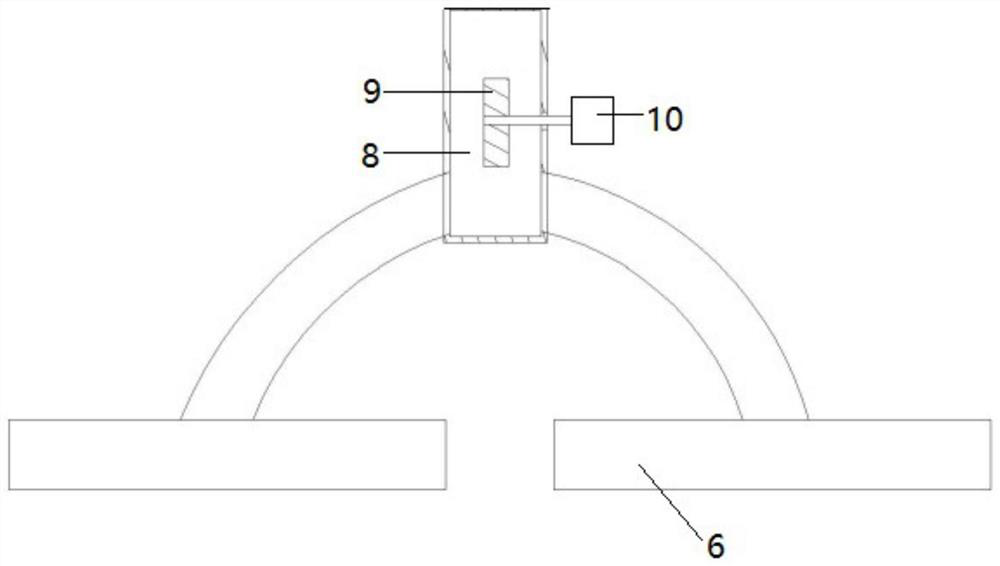
[0034] Such as figure 1 , Figure 5 The illustrated embodiment is a wire harness dyeing device, which includes a pool body 1 with an open upper end, a solution stirring device 2 installed in the pool body, a heating device 3 installed on the pool body, and four lighting fixtures located outside the pool body. Lamp 4, an upwardly arched concave mirror 5 located above the pool body; Figure 7 As shown, each illuminating lamp is arranged in an annular lampshade 201 surrounding the pool body, and a vacuum pump 202 is provided on the annular lampshade. The annular lampshade is connected to the ground through a lifting device 203, and also includes two suction covers 6 as shown in the figure. , each suction hood is provided with a suction pump, and each suction hood is connected with the exhaust pipe 8, and the exhaust pipe is provided with an impeller 9, and the rotating shaft of the impeller is connected with the worm gear structure 10, and the turbine of the worm gear structure ...

Embodiment 2

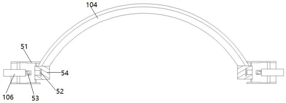
[0050] Embodiment 2 includes all structure and method parts of embodiment 1, such as image 3 As shown, the worm gear of embodiment 2 is meshed with the gear, and the rotating shaft of the gear is connected with another flexible shaft 106; the two ends of the arc brush are connected with the concave mirror through the fixed housing 51, and each fixed housing is provided with an arc brush. The fixed block 52 that is fixedly connected, the fixed block is rotatably connected with the fixed shell, and each flexible shaft is all rotatably connected with the corresponding fixed shell, and a permanent magnet 53 is arranged in each flexible shaft end, and a permanent magnet 53 is arranged in each fixed block. There are electromagnets 54, both of which are electrically connected to the controller.

[0051] The controller alternately controls the two electromagnets to be energized, so that the two flexible shafts are alternately connected and disconnected with the arc-shaped brush, so t...


PUM


Abstract

The invention discloses a wire harness dyeing device and method, comprising a pool body with an open upper end, a solution stirring device arranged in the pool body, a heating device arranged on the pool body, several lighting lamps arranged outside the pool body, and An upward arched concave mirror above the pool body; each lighting lamp is not in the ring lampshade surrounding the pool body, the ring lampshade is provided with a vacuum pump, and the ring lampshade is connected to the ground through a lifting device. The invention has the characteristics that the lamp is not easy to be corroded by steam and ensures the service life of the lamp.

Description

technical field [0001] The invention relates to the technical field of dyeing devices, in particular to a wire bundle dyeing device and method with good light. Background technique [0002] Usually, the wire harness is put into a dyeing pool filled with a dye solution for dyeing. At high temperature, the wire harness is easier to color and the dyeing time will be shortened. Therefore, the dye solution needs to be heated, and a large number of wire harnesses need to be processed at one time during the dyeing process. However, due to the volatilization of a large amount of steam, the water vapor above the dyeing pool is too heavy, which is not suitable for installing lamps. It is very difficult to observe the coloring of the wire harness in the dyeing pool. It is prone to uneven dyeing, and the undyed wire harness can only be dealt with at a reduced price, resulting in economic losses. Contents of the invention [0003] The object of the present invention is to provide a wi...

Claims


Application Information

Patent Timeline
Patent Type & Authority Patents(China)
IPC IPC(8): D06B1/00D06B23/20D06B23/22D06B23/30
CPCD06B1/00D06B23/20D06B23/205D06B23/22D06B23/30
Inventor 不公告发明人
Owner 永春县产品质量检验所福建省香产品质量检验中心国家燃香类产品质量监督检验中心福建
Learn More