Intelligent control system for indoor illumination

An intelligent control system and indoor lighting technology, applied in the direction of energy-saving control technology, electrical components, etc., can solve the problems of inconvenient control, poor lighting effect, and failure to achieve intelligence, and achieve the effect of improving intelligence and good entertainment effects

Pending Publication Date: 2020-12-01
ZHEJIANG SHUREN COLLEGE ZHEJIANG SHUREN UNIV
View PDF3 Cites 0 Cited by
  • Summary
  • Abstract
  • Description
  • Claims
  • Application Information

AI Technical Summary

Problems solved by technology

[0004] The purpose of the present invention is: in order to solve the problem that the lighting structure generally installed in the house today requires people to control the lighting switch, and it is inconvenient to control the brightness adjustment and opening and closing of each lighting lamp, and at the same time it is not intelligent and the lighting effect is not good. Good, nowadays, in order to facilitate people's lighting requirements, many remote-controlled lights have also appeared. When people use the lights, they can remotely control the lights through the remote control, so as to control the lights. Although this method replaces People directly touch the switch to control, but the control of lighting still needs manual intervention, which has not yet achieved complete intelligence. In order to adapt to the development pace of modern technological life, an intelligent control system for indoor lighting is needed. For indoor lighting In order to solve the problem of intelligent control of lamps, an intelligent control system for indoor lighting is proposed

Method used


Image

  • Intelligent control system for indoor illumination
  • Intelligent control system for indoor illumination
  • Intelligent control system for indoor illumination

Examples


Embodiment Construction

[0037] The following will clearly and completely describe the technical solutions in the embodiments of the present invention with reference to the accompanying drawings in the embodiments of the present invention. Obviously, the described embodiments are only some, not all, embodiments of the present invention. Based on the embodiments of the present invention, all other embodiments obtained by persons of ordinary skill in the art without creative efforts fall within the protection scope of the present invention.

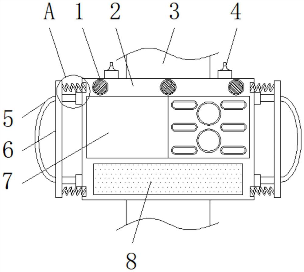
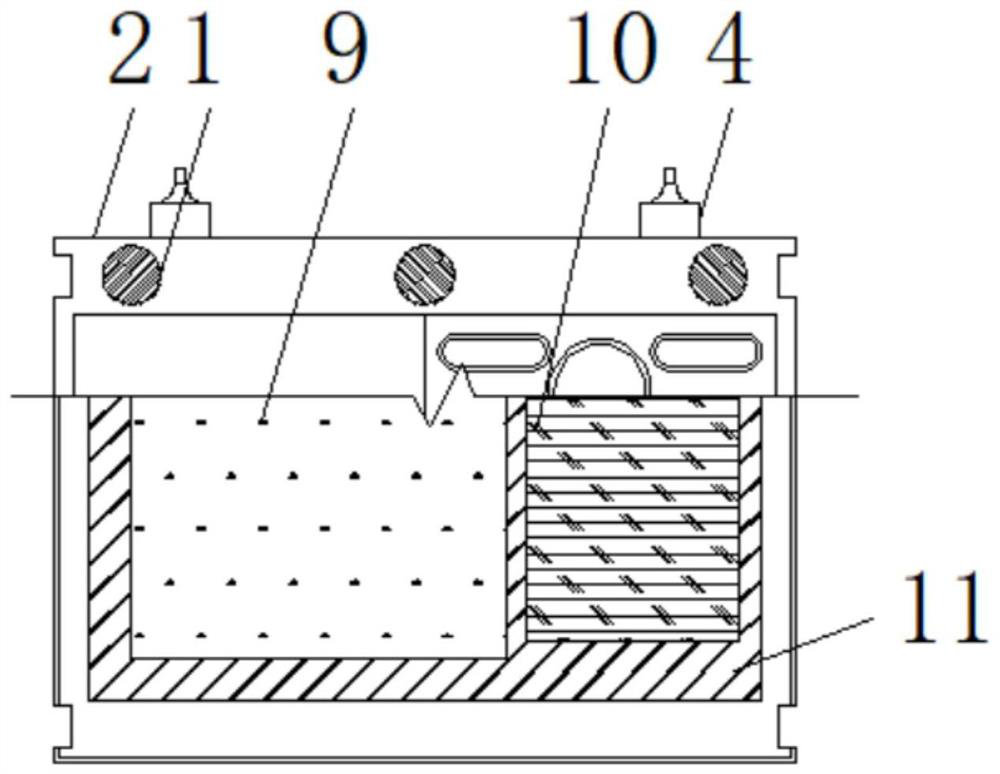
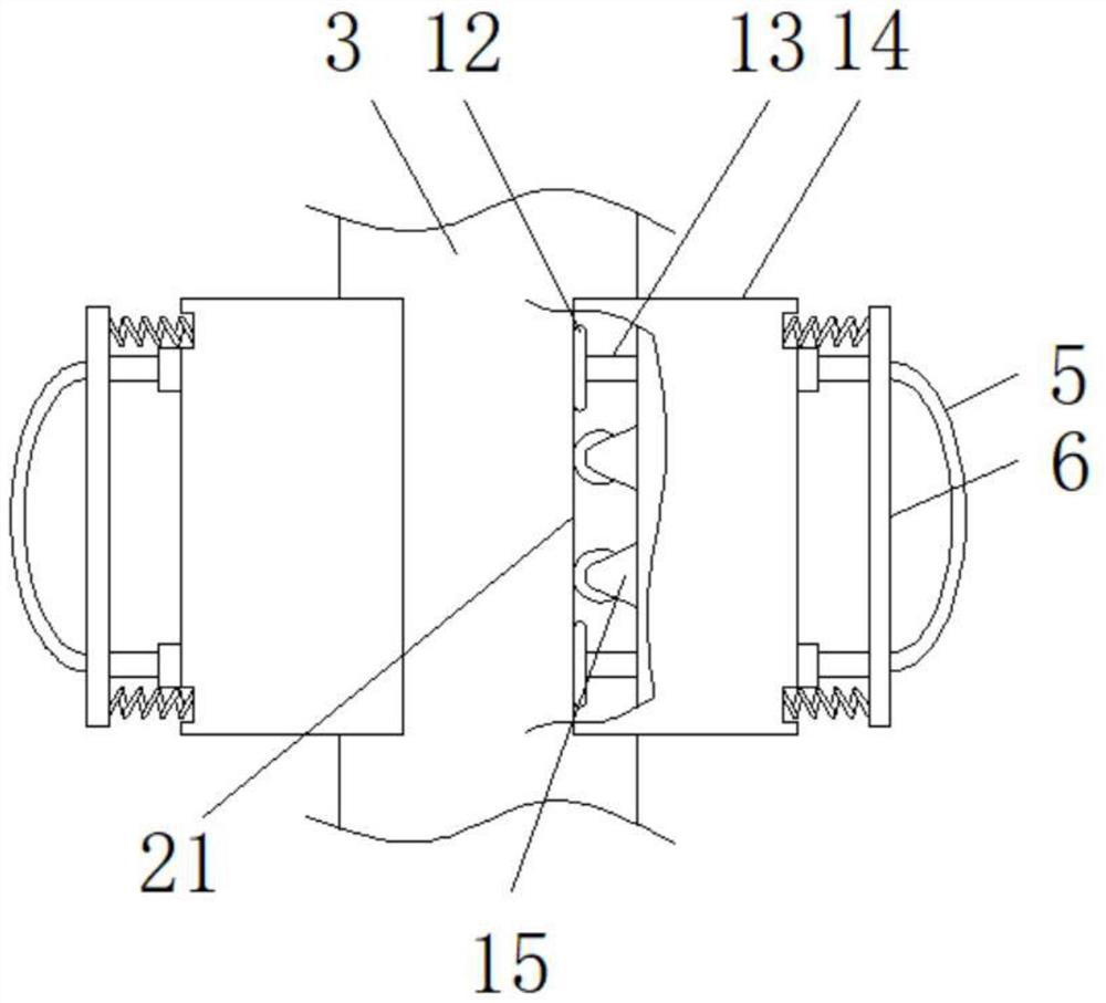
[0038] see Figure 1-7, the present invention provides a technical solution: an intelligent indoor lighting control system, including a controller body 2, an electric board 11, a positioning shaft 13, a rear mounting shell 14, a data monitoring module 19 and a time management module 20, the controller The main body 2 is slidably installed on the installation column 3 through the rear installation shell 14 fixedly installed on the outer wall of the rear side on one ...


PUM


Abstract

The invention discloses an intelligent control system for indoor illumination and belongs to the field of indoor illumination control. The system comprises a controller main body, an electric board, apositioning shaft, a rear mounting shell, a data monitoring module and a time management module; the controller main body is slidably mounted on a mounting column through the rear mounting shell fixedly mounted on the outer wall of the rear side of one side of the controller main body; the electric board is fixedly mounted in the controller main body. According to the system of the invention, a light sensor is arranged in the control system; the light sensor can effectively monitor the indoor light intensity, so that brightness adjustment and on-off adjustment can be effectively carried out on an indoor illuminating lamp according to the indoor light intensity. Compared with a traditional manual control illuminating lamp, the intelligent control system works more intelligently, does not need manual management; meanwhile, the time management module is arranged in the control system, different time periods are set in the time management module; when timing of a timing module reaches thetime periods, control logic can be converted, and the intelligence of the system is further improved.

Description

technical field [0001] The invention belongs to the technical field of indoor lighting control, in particular to an intelligent control system for indoor lighting. Background technique [0002] Lighting refers to the process of using light sources to illuminate living and working places. Nowadays, with the development of science and technology, lighting methods have become diverse. The main purpose of lighting is to create good visibility and a more comfortable environment. In modern life, a variety of lighting structures are generally installed indoors for lighting. The types of lights in different rooms are different, and the overall functions of different lights are also different. [0003] Nowadays, the lighting structure generally installed in the house requires people to control the lighting switch. It is inconvenient to control the brightness and opening and closing of each lighting lamp. At the same time, it is not intelligent and the lighting effect is not good. Now...

Claims


Application Information

Patent Timeline
IPC IPC(8): H05B47/11H05B47/12H05B47/16
CPCH05B47/11H05B47/16H05B47/12Y02B20/40
Inventor 吴凡
Owner ZHEJIANG SHUREN COLLEGE ZHEJIANG SHUREN UNIV
Why Eureka
Try Eureka