
Engine pull rod type variable valve device

A tie rod type, engine technology, applied in the direction of engine components, machines/engines, valve devices, etc., to achieve high-speed efficiency, increase service life, and continuous linear torque output

Pending Publication Date: 2019-02-15
JILIN UNIV
View PDF0 Cites 0 Cited by
  • Summary
  • Abstract
  • Description
  • Claims
  • Application Information

AI Technical Summary

Problems solved by technology

[0006] The technical problem to be solved by the present invention is the problem that the valve lift of the existing engine cannot be continuously changed with the working conditions, and an engine tie-rod valve device that can realize continuously variable valve lift is provided

Method used


Image

  • Engine pull rod type variable valve device
  • Engine pull rod type variable valve device
  • Engine pull rod type variable valve device

Examples


Embodiment Construction

[0045] specific implementation plan

[0046] The present invention is described in detail below in conjunction with accompanying drawing:

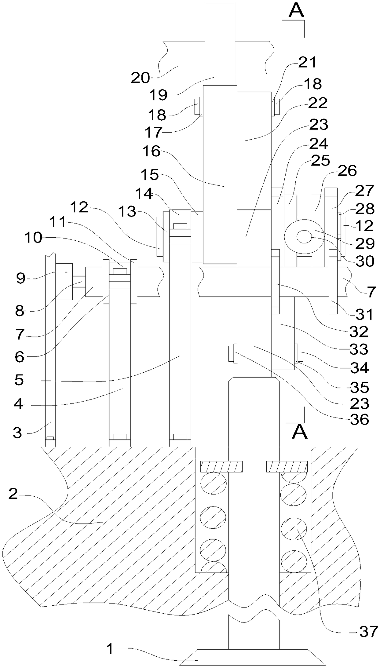
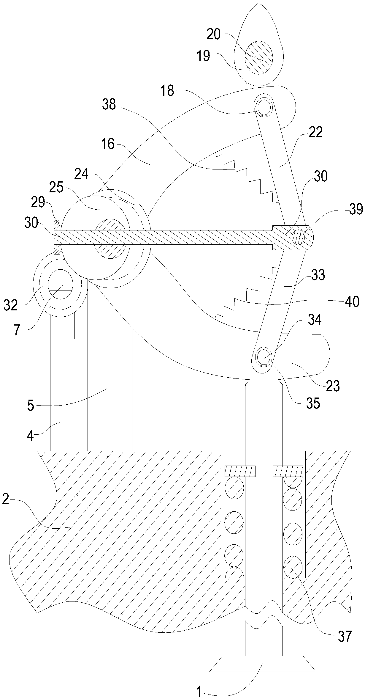
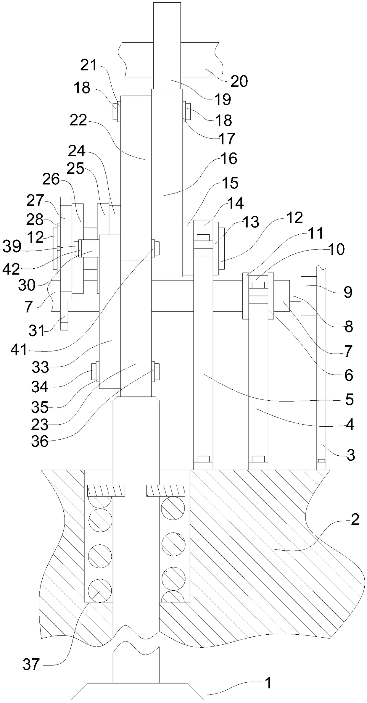
[0047] refer to Figure 1-3 , the engine rod-type variable valve device of the present invention includes the following structures: valve 1, cylinder head 2, motor mounting frame 3, control shaft bracket 4, camshaft bracket 5, limit ring platform a6, control shaft 7, motor Shaft 8, motor 9, upper cover plate a10, limit ring platform b11, rocker arm shaft 12, limit ring platform c13, upper cover plate b14, limit ring platform d15, rocker arm a16, snap ring a17, pin shaft a18 , cam 19, camshaft 20, snap ring b21, push rod a22, rocker arm b23, gear a24, eccentric ring block a25, eccentric ring block b26, gear b27, snap ring c28, ring block 29, pull rod 30, gear c31 , Gear d32, push rod b33, pin b34, snap ring d35, snap ring e36, valve spring 37, push rod return spring a38, pin shaft c39, push rod return spring b40, snap ring f41, snap ring ...


PUM


Abstract

The invention discloses an engine pull rod type variable valve device which mainly comprises a cam, a motor, a control shaft, a gear transmission and a rocker arm. The pull rod type variable valve device is fixed on a cylinder cover; when the engine rotating speed changes, an eccentric ring block a25 and an eccentric ring block b26 are driven by the motor 9 to move to drive a push rod 30 to advance and return, the angle between a push rod a22 and a push rod b33 is changed, and movement of the cam 19 is used in cooperation, so that the problem that the valve stroke of an engine cannot be adjusted and controlled under different working conditions is solved, the valve stroke is continuously changed, sufficient exhausting is promoted, mixing is improved, the torque of the engine under the low-speed working condition and efficiency of the engine under the high-speed working condition are better improved, and the fuel economy, dynamic property and emission performance of the engine are better improved.

Description

technical field [0001] The invention relates to an automobile engine component or equipment, in particular to an engine tie-rod variable valve device. Background technique [0002] The valve mechanism of the engine is an important part of the engine. Its main function is to control the opening time and duration of the valve and the closing time of the valve according to the working cycle of each cylinder, so as to realize the fresh air entering the cylinder during the cylinder ventilation process and The discharge of exhaust gas provides a reliable source of power for the cycle of the engine. [0003] The valve lift of the traditional engine valve train is fixed and invariable, that is to say, there is only one cam profile of the camshaft, which determines that the engine in this case cannot operate at both high speed and low speed. With a good response, the engine neither gets high-speed efficiency nor low-speed torque. [0004] In view of this, after improvement, some en...

Claims


Application Information

Patent Timeline
Patent Type & Authority Applications(China)
IPC IPC(8): F01L13/00F01L9/04F01L9/22
CPCF01L13/0026F01L9/22F01L9/20
Inventor 解方喜李晓娜洪伟刘洪涛杨野周思佟孙博赵志宏周遊石卜从王斌郑文良蓝大舜王鹏辉
Owner JILIN UNIV
Learn More