Air source dryer for cotton drying

An air source and dryer technology, applied in dryers, drying, drying gas layout and other directions, can solve the problems of large energy consumption, large labor consumption, large weather influence, etc., and achieve resource saving and simple structure. Effect

Inactive Publication Date: 2019-02-15
合肥宽信机电有限公司
View PDF7 Cites 1 Cited by
  • Summary
  • Abstract
  • Description
  • Claims
  • Application Information

AI Technical Summary

Problems solved by technology

Natural drying mainly relies on sunlight to achieve the purpose of removing moisture from cotton, but natural drying is greatly affected by the weather. At the same time, a large amount of cotton is naturally dried, which requires a lot

Method used


Image

  • Air source dryer for cotton drying

Examples


Embodiment Construction

[0014] In the description of the present invention, it should be understood that the terms "first", "second", and "third" are only used for descriptive purposes, and cannot be interpreted as indicating or implying relative importance or implicitly indicating the indicated technical features quantity.

[0015] The following will clearly and completely describe the technical solutions in the embodiments of the present invention with reference to the accompanying drawings in the embodiments of the present invention. Obviously, the described embodiments are only some, not all, embodiments of the present invention. Based on the embodiments of the present invention, all other embodiments obtained by persons of ordinary skill in the art without making creative efforts belong to the protection scope of the present invention.

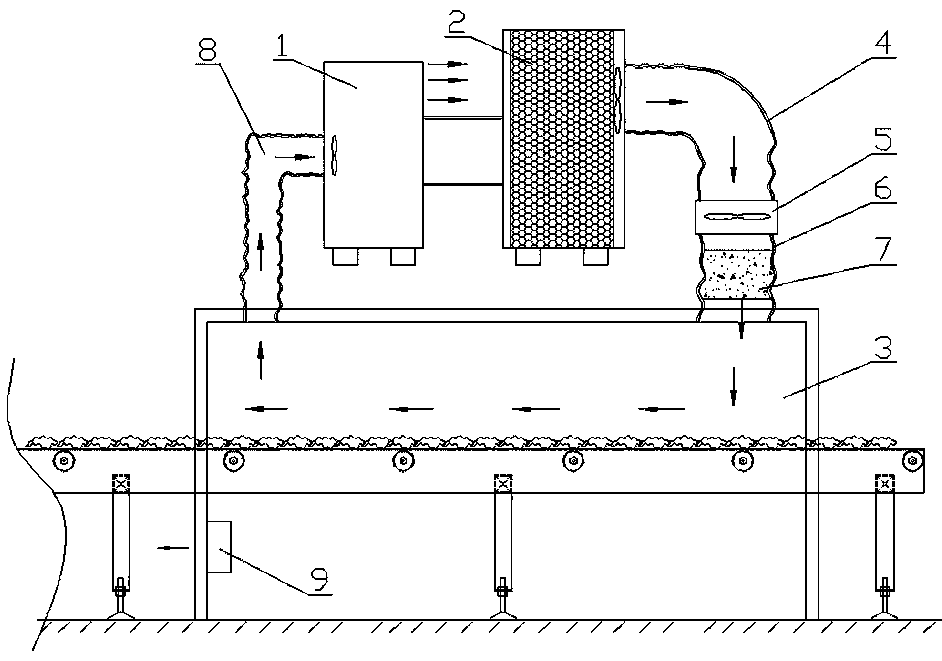
[0016] Such as figure 1 As shown, an air source dryer for cotton drying includes an evaporator (1), a heat exchanger (2), a first air duct (4), an axial flow f...


PUM


Abstract

The invention discloses an air source dryer for cotton drying. The air source dryer for cotton drying comprises an evaporator, a heat exchanger, a first air hose, an axial flow fan, a second air hoseand a third air hose, and a loop connection is formed between the evaporator and the heat exchanger through a copper pipe; one end of the first air hose is fixedly connected with an air outlet of theheat exchanger, the other end of the first air hose is fixedly connected with one end of the axial flow fan, the other end of the axial flow fan is fixedly connected with one end of the second air hose, and the other end of the second sir hose is connected with a drying chamber; the second air hose is internally provided with a drying agent layer; and the drying chamber is internally provided witha dehumidifying machine, and two ends of the third air hose communicate with a heat absorbing endof the evaporator and the drying chamber correspondingly. The air source dryer for cotton drying is ofa simple structure, by arranging the evaporator and the heat exchanger to cooperate and work, the purpose of drying is achieved, and precious resources are saved.

Description


Claims


Application Information

Patent Timeline
Owner 合肥宽信机电有限公司
Why Eureka
Try Eureka