Eureka AIR delivers breakthrough ideas for toughest innovation challenges, trusted by R&D personnel around the world.

Drying structure for dish-washing machine liner

A dishwasher liner and drying technology, which is applied in the direction of tableware washing machine/rinsing machine, tableware washing machine/rinsing and rinsing machine parts, sustainable buildings, etc., can solve the problem of low condensation efficiency, long drying time, unfavorable and other problems, to achieve the effect of remarkable drying effect, convenient operation and simple structure

Pending Publication Date: 2018-11-06
VATTI CORP LTD
View PDF0 Cites 5 Cited by
  • Summary
  • Abstract
  • Description
  • Claims
  • Application Information

AI Technical Summary

Problems solved by technology

[0003] At present, natural drying is generally used for drying tableware in household dishwashers. The drying performance is improved by increasing the rinsing temperature, which is not conducive to reducing energy consumption, and the drying time is too long
There is also an internal circulation drying device, which draws hot and humid air to flow in the condenser to cool and liquefy, thereby reducing the air humidity and improving the drying effect. The condensation efficiency of the device is not high, and the condensed air is discharged back into the inner tank, which will increase the internal humidity, which is not conducive to the drying of tableware
There is also an external circulation drying device, which directly extracts the hot and humid air inside the dishwasher and discharges it to the outside of the dishwasher. However, the hot and humid air discharged by it is easy to cause rust on the shell, moldy and rotten cabinets, and damp kitchen floors. Take away the heat inside the dishwasher, which is not conducive to reducing energy consumption

Method used


Image

  • Drying structure for dish-washing machine liner
  • Drying structure for dish-washing machine liner
  • Drying structure for dish-washing machine liner

Examples


Embodiment Construction

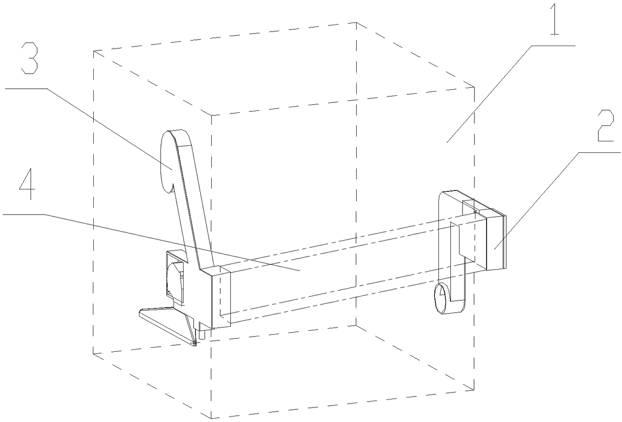
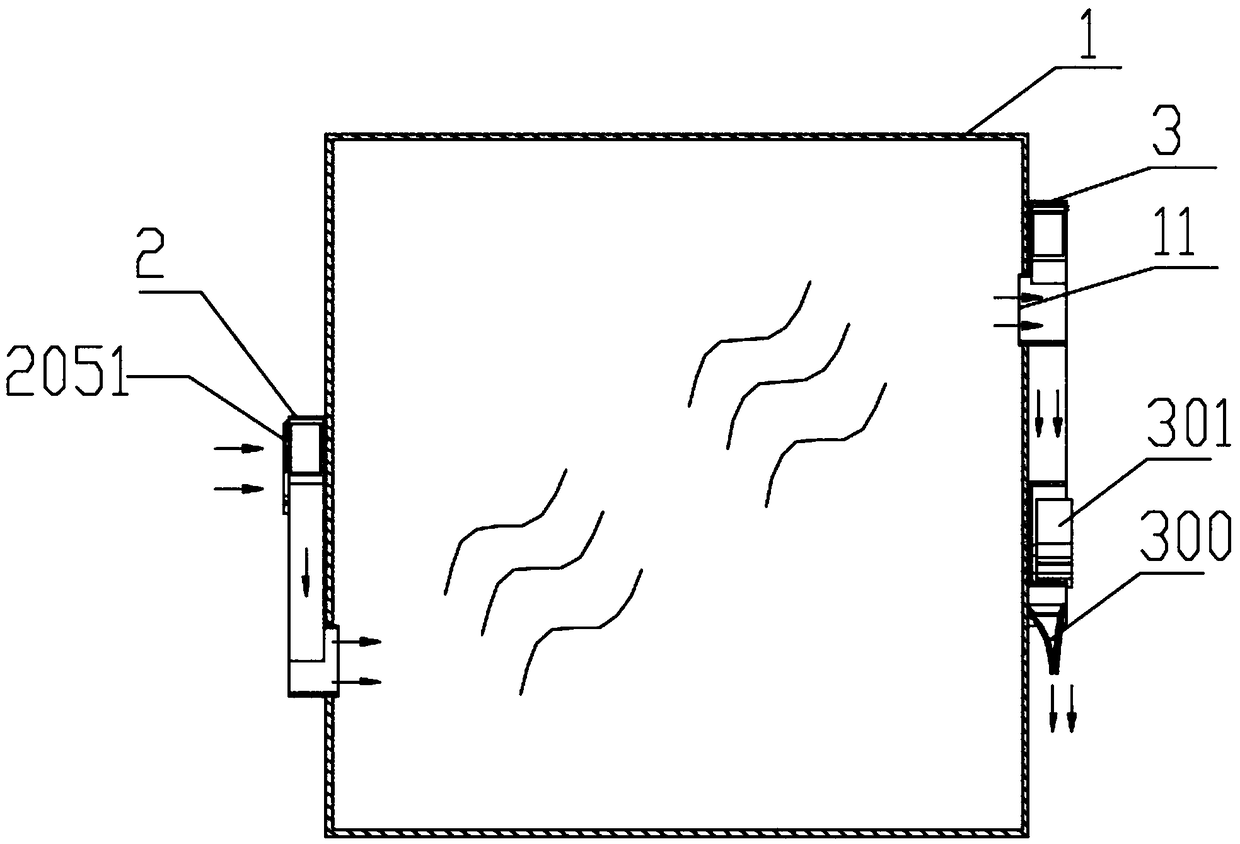
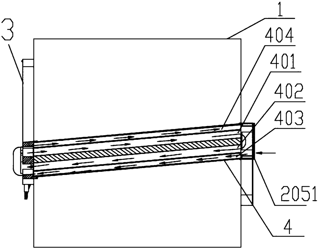
[0025] The specific structure of the present invention is as Figure 1-5 As shown, a drying structure of a dishwasher inner container 1 includes an air outlet assembly 3 and an air intake assembly 2 arranged on the inner container 1. Specifically, the outer wall of the dishwasher inner container 1 is provided with an air outlet assembly 3 The dishwasher liner 1 has an air outlet 11 communicating with the air outlet assembly 3, the other side wall of the dishwasher liner 1 is provided with an air intake assembly 2, and the dishwasher liner 1 has an air inlet 10 connected to the air inlet The lower ends of the gas components 2 communicate. Through the air intake fan 202 arranged on the air intake assembly 2 and the air outlet fan 301 of the air outlet assembly 3, the air intake fan 202 is used to deliver air to the dishwasher liner 1 through the air intake assembly 2, in other words During the drying process, external low-humidity air is forcibly introduced into the inner tank ...


PUM


Abstract

The invention discloses a drying structure for a dish-washing machine liner. An air inlet and an air outlet are formed in the liner, and a height difference exists between the air inlet and the air outlet. The drying structure also comprises an air inlet component, the air inlet component comprises an air inlet draught fan and a filter device, the air inlet component is communicated with the air inlet, and the air inlet component is used for sucking gas into the liner. The drying structure also comprises an air outlet component, the air outlet component is connected with the air outlet, the air outlet component is used for discharging gas inside the liner, and the air outlet component is internally provided with a condenser and an air outlet draught fan. A heat exchange device is connectedbetween the air outlet component and the air inlet component, so that gas entering into the liner is preheated, and in addition, the temperature of the exhaust gas of the liner can also be reduced; and the drying structure has the characteristics of simple structure and obvious drying effect, and has the advantage of being beneficial to reduction of energy consumption.

Description

technical field [0001] The invention relates to the technical field of household appliances, in particular to a drying structure for a dishwasher inner tank. Background technique [0002] During the drying process of the dishwasher, the water on the tableware volatilizes when heated to produce water vapor, and the water vapor generates condensed water when the side wall of the inner tank is cooled, which reduces the air humidity, so that the residual water of the tableware can continue to volatilize and dry. [0003] At present, the drying routine of domestic dishwasher tableware adopts natural drying, and the drying performance is improved by increasing the rinsing temperature, which is not conducive to reducing energy consumption, and the drying time is too long. There is also an internal circulation drying device, which draws hot and humid air to flow in the condenser to cool and liquefy, thereby reducing the air humidity and improving the drying effect. The condensation...

Claims


Application Information

Patent Timeline
IPC IPC(8): A47L15/48
CPCA47L15/481A47L15/483A47L15/486A47L15/488Y02B40/00
Inventor 徐术荣王豪杰庞士魁潘叶江
Owner VATTI CORP LTD
Why Eureka
Eureka Blog
Learn More