Freely-falling-body gravity acceleration measurement device based on capacitive sensors

A capacitive sensor and gravitational acceleration technology, which is applied in the field of experimental instruments, can solve the problems of long experimental preparation time, low experimental success rate, and failure to be detected, and achieve the effects of saving experimental preparation time, efficient experimental process, and improving accuracy

Active Publication Date: 2019-02-15
XUZHOU NORMAL UNIVERSITY
View PDF10 Cites 6 Cited by
  • Summary
  • Abstract
  • Description
  • Claims
  • Application Information

AI Technical Summary

Problems solved by technology

However, in the experiment, it first takes a lot of time to adjust the position of the falling path of the steel ball, so that the vertical lower point of the steel ball corresponds to the light path emitted and received by the photoelectric gate, so that the steel ball falls through the light path of the photoelectric gate and reaches the photoelectric gate. The triggering of the gate, and then achieve the purpose of separately triggering the start and stop timing, but this requires a lot of experimental preparation work
At the same time, the falling trajectory of the steel ball often deviates from the light path emitted and received by the photogate during the falling process, which leads to the fact that the steel ball cannot be detected during the falling process, resulting in the lack of time t experimental data in the free fall experiment, which leads to the failure of the experiment
Therefore, the current experimental device requires a lot of time to adjust the experiment before the experiment. During the experiment, the falling steel ball is often missed by the photoelectric gate, resulting in timing failure. The current experimental device has too long preparation time for the experiment and low success rate of the experiment. shortcoming

Method used


Image

  • Freely-falling-body gravity acceleration measurement device based on capacitive sensors
  • Freely-falling-body gravity acceleration measurement device based on capacitive sensors
  • Freely-falling-body gravity acceleration measurement device based on capacitive sensors

Examples


Embodiment Construction

[0025] Embodiments of the present invention are described in detail below, examples of which are shown in the drawings, wherein the same or similar reference numerals designate the same or similar elements or elements having the same or similar functions throughout. The embodiments described below by referring to the figures are exemplary and are intended to explain the present invention and should not be construed as limiting the present invention.

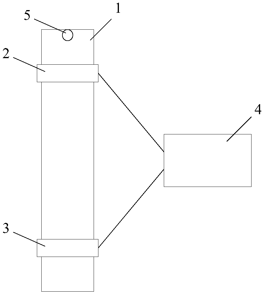
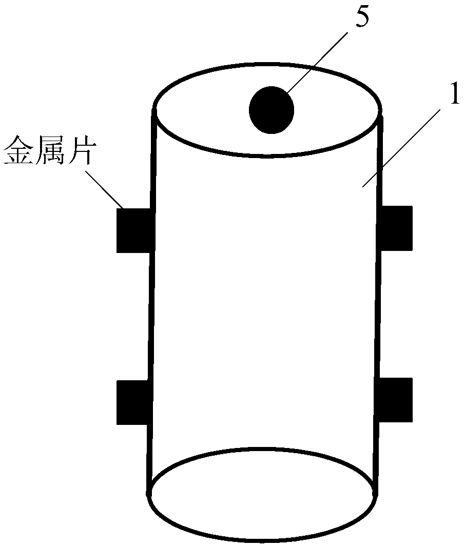
[0026] Such as figure 1 As shown, the free-fall gravitational acceleration measurement device based on the capacitance sensor of the embodiment of the present invention includes an experimental column 1, a first capacitance sensor 2 and a second capacitance sensor 2 that are arranged at different heights of the experimental column 1 and are separated by a preset distance. Sensor 3, processing module 4. Wherein, the experimental column 1 is vertically placed for the metal detection object 5 to freely fall from top to bottom in th...


PUM


Abstract

The invention discloses a freely-falling-body gravity acceleration measurement device based on capacitive sensors. The device includes: an experiment tube column, which is vertically placed to enablea metal detection object to carry out freely-falling movement from a top to a bottom in the experiment tube column; a first capacitive sensor and a second capacitive sensor, which are disposed at different heights of the experiment tube column, are separated with a preset distance, and are used for generating induction signals when the metal detection object respectively falls to the correspondingheights; and a processing module, which is respectively connected with the first capacitive sensor and the second capacitive sensor, and is used for processing the induction signals generated by thefirst capacitive sensor and the second capacitive sensor, respectively obtaining corresponding falling-edge triggering pulse signals, and obtaining a falling time of the metal detection object in thepreset distance according to the falling-edge triggering pulse signals, which correspond to the first capacitive sensor and the second capacitive sensor, to facilitate a process of calculating gravityacceleration according to the preset distance and the falling time.

Description

technical field [0001] The invention relates to the technical field of experimental instruments, in particular to a free-fall gravitational acceleration measurement device based on a capacitance sensor. Background technique [0002] The experiment of measuring the acceleration of gravity by the free fall method is currently one of the basic experiments of undergraduate physics subjects, and has become an indispensable part of the current university physics experiments. It detects the magnitude of the free-fall gravitational acceleration g through the free-fall method of the object, and currently occupies an important position in the teaching and scientific research of university physics. [0003] Since the calculation of the acceleration of gravity g needs to measure the vertical distance of the object falling for a distance of s and the time interval t for the object to pass through this distance, the experimenter can obtain the magnitude of the acceleration of gravity g wh...

Claims


Application Information

Patent Timeline
Patent Type & Authority Applications(China)
IPC IPC(8): G01V7/14G01D5/24
CPCG01D5/2405G01V7/14
Inventor 魏明生孙红冯雨
Owner XUZHOU NORMAL UNIVERSITY
Why Eureka
Try Eureka